Keywords
|
| Bio-impedance, heart rate, synchronization, impedance analyzer |
INTRODUCTION
|
| An electrical impedance signal from human body can be obtained due to blood volume change and blood resistivity change. This electrical impedance from human body is called bio-impedance. Bio-impedance is the opposition offered by human tissues to the current flowing through them. In this paper, bio-impedance is used to detect heart rate. The heart beat comprises of systole and diastole activity. During systole, the left ventricle accelerates a volume of blood through the ascending aorta and during diastole the ejected blood volume accelerates through the descending aorta due to its compliance. These volume changes in blood result in bio-impedance variations. Thus, bio-impedance variations can be processed to build a signal used to detect number of heart beats in specific time. |
LITERATURE SURVEY
|
| Bio-impedance is a technique used since 1948 in the field of biomedical research along with application development. Rafael Gonzalez-Landaeta, Delia H. Diaz, Oscar Casas and Ramon Paras Arney are some of the contributors to the research in identifying the relationship between bio-impedance measurement and heart diseases [1, 2, 4, 5]. Techniques are being identified and developed to detect heart rate using plantar electrode, single foot plantar electrode and weighing machine using bio-impedance analysis [1, 4, 5]. Some studies suggest application of impedance analyzer AD 5933 for bioimpedance measurement. Various methods of bio-impedance signal detection and processing are analyzed for detection of heart rate to implement the method of heart rate detection presented in this paper. Analysis of electrocardiogram signal is one of the established techniques for detection of heart rate. |
| The plantar electrode method can be used for bio-impedance measurement which can determine the heart rate precisely [1]. Heart rate is detected from arterial volume change. High signal to noise ratio as well as its estimation is a part of bioimpedance signal analysis. Electro cardiogram and bio-impedance signals are compared for healthy subjects with great success. An alternative method is to detect the heart rate from bio-impedance measured in a single foot while standing on a bathroom weighting scale intended for bio-impedance analysis [4]. The electrodes built in the weighing scale are used to apply a 50 KHz voltage between the outer electrode pair and to measure the drop in the voltage across the inner electrode pair. It is observed that the QRS peak in electro cardiogram correspond to bio-impedance signal peak. The heart rate can be detected for a subject that stands on a common electronic weighing scale [5]. The detection relies on sensing force variations related to the blood acceleration in the aorta and does not require any sensors attached to the body. This method is applied to three different weighing scales and estimated whether their sensitivity and frequency response suited heart rate detection. A pulse detection system is designed which can sense force variations about 240 mN. To validate the method, the electro cardiogram and the force signal can be simultaneously recorded. In all the methods for heart rate detection, synchronous demodulator plays vital role by demodulating the bio-impedance signal from current carrier. Exhaustive research is carried out on synchronous demodulation and synchronous sampling for achieving high CMRR in signal processing methods [2, 8]. In analog differential synchronous demodulator for ac signals, the signal is synchronously demodulated using the floating-capacitor technique that yields a very high CMRR [2]. There are several other methods of synchronous demodulation but floating capacitor method carries more importance due to high signal to noise ratio. In the system presented in this paper, impedance analyzer is used for getting bio-impedance signal. The methods and systems involving impedance analyzer as well as microcontroller units are studied for the implementation of presented work [7]. Wavelet thresholding methods are used for noise removal [3]. In the signal denoising, wavelet coefficients are threshold in order to remove their noisy part. These methods do not assume any nature of the signal, permit discontinuities and spatial variation in the signal and exploit the spatially adaptive multi-resolution of the wavelet transform [3]. Extensive literature study on bio-impedance and impedance analyzer is carried out and relative work is explored in order to present this technique for heart rate measurement using bio-impedance. |
MEASUREMENT PRINCIPLE
|
| The systole and diastole activities lead to formation of peaks in bio-impedance signal. It leads to considerable volume change in artery. This major change is represented by bio-impedance signal peak and QRS complex in ECG signal. The relation between arterial volume change and impedance variations caused by blood resistivity and blood volume is given by following equation. |
 (1) (1) |
| In equation (1) ΔV is the volume change in arteries, L the length of the section of arteries between the voltage electrodes, ρ the blood resistivity, and Z0 the basal impedance of the non pulsatile tissues. Zρ is the impedance variations due to the blood resistivity change. Zv is the impedance variation due to the volume change [1]. |
| For measuring bio-impedance, the carrier current of known amplitude and frequency is passed through human body using electrode. The current signal is referred to as excitation signal. The carrier signal gets modulated due to impedance of human tissues and this modulated signal is called bio-impedance signal. The bio-impedance signal can be detected at the output by using electrode. If current passed through tissues is defined by equation (2) |
 (2) (2) |
| and voltage measured for detected signal is defined by equation (3) |
 (3) (3) |
| then the equation (3) can be written as equation (4). |
 (4) (4) |
| We can write resistance R(t) as in equation (5). |
 (5) (5) |
| The reactance X(t)can be written as in equation (6). |
 (6) (6) |
| Also IR(t) and IX(t) are in-phase and quadrature components of v(t), respectively. The impedance can be calculated by using equation (7). |
 (7) (7) |
| R(t) and X(t) are in-phase and quadrature component of Z(t), respectively. In-phase component is resistive component comprising of real part of bio-impedance and quadrature component is reactive component comprising imaginary part of bio-impedance [2, 8]. |
| Four electrode bio-impedance measurement technique is used to get the signal. In this technique, current is passed through the body. It leads to variations in voltage due to impedance variations caused by changes in blood resistivity and blood volume. Bio-impedance signal will represent these voltage variations. Thus, bio-impedance signal represents arterial volume change which is responsible for occurrence of heart beat. |
MATERIALS AND METHODS
|
| Various measurement blocks used are explained in this section. |
Electrodes
|
| Four electrode measurement technique is for detecting the signal. Two electrodes are used for injecting the current. This current will vary due to impedance variations caused by arterial volume change. The output voltage generated due to current flow is measured by using another pair of electrode. |
Signal detector
|
| Synchronous demodulation is used in detection of bio-impedance signal from current carrier. There are two methods for detecting signals. One method involves synchronous sampling by using AD630 demodulator [8]; while in another method sample and hold circuit is used for synchronous demodulation. LTC 1043 and 1μF floating capacitor is used for realizing sample and hold circuit [2]. This paper explains the use of AD5933 impedance converter for capturing signal where discrete Fourier transform is used to detect the signal. |
| The AD5933 is a high precision impedance converter system solution that combines an on-board frequency generator with a 12-bit, 1 MSPS, analog-to-digital converter. AD5933 can generate excitation signal which can have maximum frequency of 100 KHz. It has programmable frequency sweep capacity and serial I2C interface. It can measure impedance from 1KΩ to 10 MΩ. The AD5933 can accurately measure a range of impedance values to less than 0.5% of the correct impedance value with 2.7 V to 5.5 V as supply voltage. |
| Impedance conversion in AD5933 comprises of three stages namely transmit and receive stages and discrete Fourier transform operation. |
Transmit stage
|
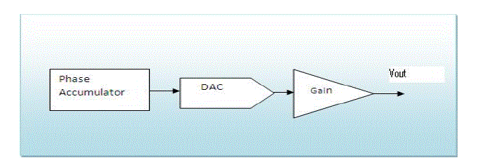
| As shown in Figure 1, transmit stage consists of direct digital synthesizer core that provides output excitation voltage of particular frequency. Direct digital synthesizer core is used for creating waveforms from a single fixed frequency clock. As shown in Figure 1, direct digital synthesizer core consist of 27-bit phase accumulator that provides excitation signal of particular frequency as output. AD5933 permits the user to perform a frequency sweep. The user can decide the start frequency. The number of increments in frequency sweep and amount of frequency increment can also be decided by the user. |
| Registers provided in the on board RAM are programmed using software so as to define all three frequency sweep parameters. The direct digital synthesizer output signal is passed through programmable gain stage to get the required peakto- peak output excitation signal. |
| This output excitation signal is passed through human body and the response signal detected using electrodes. The response signal from electrodes is fed to the receive stage. Output frequency range of 1 KHz to 100 KHz can be achieved with resolution as low as 0.1 Hz. |
Receive Stage
|
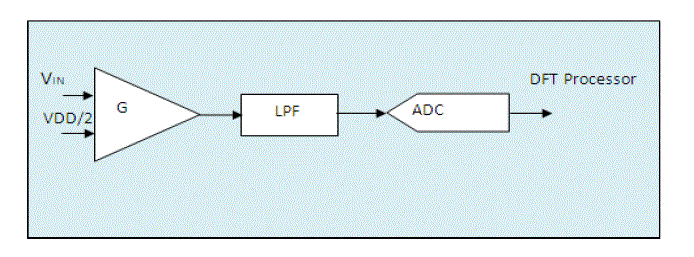
| In receive stage, current to voltage conversion takes place along with programmable gain. At this point, the impedance that is to be measured is unknown. The signal current developed across this unknown impedance flows into the VIN pin of AD5933 and develops a voltage signal at the output of the current-to-voltage converter. This voltage is amplified using programmable gain amplifier. The output signal from programmable gain amplifier is low pass filtered and given to 12 bit, 1MSPS analog-to-digital converter as shown in Figure 2. |
Discrete Fourier transform operation
|
| Discrete Fourier transform can be used to approximate any signal as the sum of infinite sine and cosine functions. The results of discrete Fourier transform operation are complex numbers which comprise of real and imaginary part. Impedance is a complex number and hence AD5933 uses discrete Fourier transform for impedance conversion. In AD5933, discrete Fourier transform is calculated for each frequency point in the sweep. Equation (8) shows the calculation of discrete Fourier transform by AD5933. |
 (8) (8) |
| In equation (8), X(f) represents power in the signal at frequency point f, x(n) the ADC output and cos( n) and sin( n) are the sampled test vectors provided by direct digital synthesizer core at frequency f. |
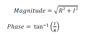
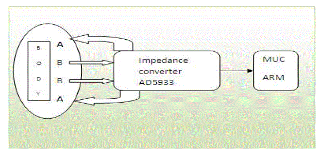
| The discrete Fourier transform returns a real and imaginary data word at each output frequency. These two values are stored in two separate registers in AD5933. After calibration the magnitude of the impedance and relative phase of the impedance at each frequency point along the sweep is easily calculated as in equation (9) and (10) respectively. This is done off chip using the real and imaginary register contents that can be read from the serial I2C interface [7]. In this paper, the bioimpedance signal is processed by interfacing AD 5933 with ARM cortex processor as shown in Figure 3. In Figure 3, A indicates current injecting electrodes and B indicates voltage measuring electrodes. |
 |
| LPCXpresso is the integrated development environment used. LPCXpresso is a low cost microcontroller development platform that provides end to end solutions enabling engineers to design their project. It includes all the tools necessary to develop high quality embedded software applications in timely and cost effective fashion. It has device specific support for ARM cortex. LPCXpresso includes cortex microcontroller software interface standard libraries and source code. |
| The signal detected from hardware is noisy. De-noising of the signal is performed by adaptive threshold algorithm. It provides large signal to noise ratio so that heart rate can be detected from signal. Wavelet transform is used for adaptive thresholding as it is much more concentrated in time [1, 3]. Wavelets allow to analyze the noise level separately at each wavelet scale and to adapt the de-noising algorithm accordingly. |
DISCUSSION
|
| If ECG and bio-impedance signal are compared every peak in bio-impedance signal can be related with the QRS complex in ECG signal. Bio-impedance signal shows variations according to systole and diastole activity. Heart rate can be estimated by applying threshold algorithm to bio-impedance signal. It results in train of pulses. Heart rate can be estimated by counting number of pulses during 10 seconds by using equation (11). |
| Heart rate = Number of pulses in 10 seconds x 6 (11) |
CONCLUSION
|
| Impedance converter like AD5933 can provide real and imaginary components of bio-impedance signal. ARM cortex processor can be effectively used to process the captures bio-impedance signal. Periodically occurring systole and diastole activity affects the bio-impedance signal. The bio-impedance signal shows clear upward and downward deflection with reference to systole and diastole activity. This leads to measurement of heart rate. |
Figures at a glance
|
 |
 |
 |
| Figure 1 |
Figure 2 |
Figure 3 |
|
References
|
- Rafael Gonzalez-Landaeta and Ramon Pallas-Areny, "Heart Rate Detection From Plantar Bioimpedance Measurements," IEEE Transactions onBiomedical Engineering, vol. 55, no. 3, pp. 1163-1167, Mar 2008.
- Ramon Pallas-Areny and Oscar Casas, "A novel synchronous demodulator for AC signals," IEEE Transactions on Instrumentation and Measurement,vol. 45, no. 2, pp. 413-416, Apr 1996.
- Rami Cohen, "Signal Denoising Using Wavelets," Department of Electrical Engineering, Technion - Israel Institute of Technology, Haifa, Feb 2012.
- Delia H. Diaz, Oscar Casas, and Ramon Pallas-Areny, "Heart Rate Detection from Single-Foot Plantar Bioimpedance measurements in a Weighing Scale," in Annual International Conference of the IEEE Engineering in Medicine and Biology Society (EMBC), Buenos Aires, Argentina, 2010, pp.6489-6492.
- R. Gonzalez-Landaeta, O. Casas, and R. Pallas-Aren, "Heart Rate Detection from an Electronic Weighing Scale," in Annual International Conferenceof the IEEE Engineering in Medicine and Biology Society (EMBS), Lyon, 2007, pp. 6283-6286.
- Padma Batra and Rajiv Kapoor, "A Novel Method For Heart Rate Measurement Using Bioimpedance," in International Conference on Advances inRecent Technologies in Communication and Computing (ARTCom), Kottayam, 2010, pp. 443-445.
- Melwin Abraham C and Prof. K. Rajasekaran, "Implementation of Bioimpedance instrument Kit in ARM7," International Journal of AdvancedResearch in Computer Science and Software Engineering, vol. 3, no. 5, pp. 1271-1273, May 2013.
- O.Casas and R.Pallas-Arney, "Signal to noise Ratio in bioelectrical impedance measurement using Synchronous Sampling," in Annual InternationalConference of the IEEE Engineering in Medicine and Biology Society. Engineering Advances: New Opportunities for Biomedical Engineers, vol. 2, Baltimore, MD, 1994, pp. 890-891.
|