Keywords
|
| SEPIC converter, DC motor, voltage multiplier, ZCS |
INTRODUCTION
|
| In ac-dc conversion system, the current drawn from the ac side has huge amount of third harmonics, so the power quality problems introduced on the ac grid is severe. Many methods are adopted to solve the low power factor and high THD. In power system, load with low power factor draws more current, so energy is wasted. Because of wasted energy, electrical utilities will charge a higher cost to customers with low power factor. The most common method used is boost type power factor correction. But there are many disadvantages such as it is not applicable for universal input voltage applications and it has low efficiency, which affect the thermal design of heat sink. Also its static gain is not enough and has high switching losses. In boost converter, voltage multiplier technique [1] is used to increase the static gain with low switching losses. A modified high power factor SEPIC [2] is used to obtain high static gain at low voltage. Due to the operation with high input current and high output voltage, the step up stage is a critical point for design of high efficiency converter [3]. Some single phase high power factor rectifiers are presented in [4-5]. High static gain and low switch voltage topology, to improve the efficiency are given in [6-7]. |
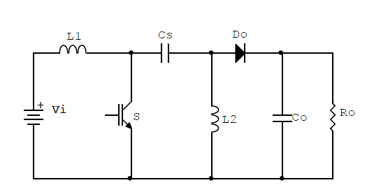
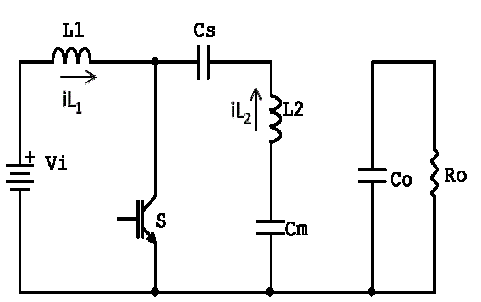
| DC-DC converters are widely used in DC motor drive applications. The input to the converter is DC voltage obtained by rectifying the grid voltage, but for its application high step up static gain and high efficiency is required. SEPIC Converter is a DC-DC converter, which is suitable for both step up and step down operation. Its input current is not pulsating and has same polarity for both buck and boost operation. Fig. 1 shows a conventional SEPIC Converter. |
MODES OF OPERATION AND WAVEFORMS
|
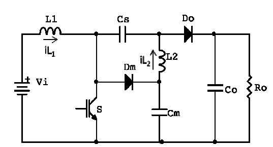
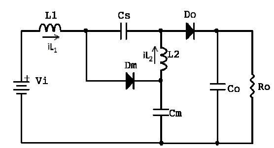
| The selected converter is Modified SEPIC Converter [2] which has many advantages than that of conventional SEPIC such as low switching voltages and high static gain. In conventional converter, the switching voltage is the sum of input and output voltage, so it has high switch voltage and low static gain and is not applicable for universal voltage applications. For avoiding these problems, diode DM and capacitor CM is used. Fig. 2 shows the modified SEPIC Converter. Due to the charging of the capacitor CM to the output voltage, the voltage across the inductor will be very high and so increasing the static gain. |
| Mode 1: Switch is off |
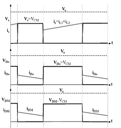
| The energy stored in the inductor during the turn on is transferred to the output. The switching voltage during this period is low and is equal to the capacitor voltage. In this case both diodes are forward biased and current through it decreases due to the charging of capacitor. |
| Mode 2: Switch is on |
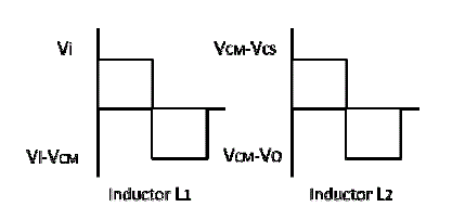
| During this period both inductors store energy. Inductor L1 stores energy from input voltage and inductor L2 stores energy from VCS-VCM (VCM > VCS). The diode D0 is reverse biased as V0 > VCS and diode DM is reverse biased due to the voltage VCM. |
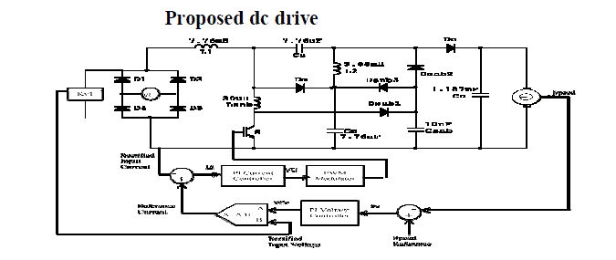
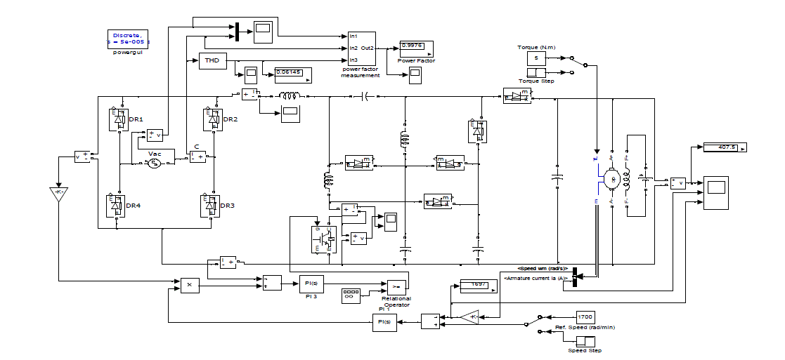
| The modified SEPIC converter has lowest duty cycle values in all range of input voltage than conventional converter. Lower duty cycle results in lower switch conduction interval. As the ton period is low, a lower current ripple is obtained in the input inductor L1. The switch voltage is lower than output voltage in all input voltage range, which will increase the converter efficiency and reduce the cos tFig.6 shows the proposed DC drive along with the ratings of the components used. The speed of the DC motor is measured and is used for controlling the switch. Lsnb is used to limit the di/dt and to provide ZCS and it will also eliminate turn on commutational losses. Csnb is used to eliminate the dv/dt of power switch voltage. Speed of the DC motor is compared with the reference speed. The error is applied to the PI controller. The result obtained is multiplied with the input voltage and the resultant obtained is reference waveform for current control loop. The reference current is made in phase with the input voltage by multiplying the unit input voltage waveform with the output of PI controller. Then it is compared with the rectified input current, so that the actual current follows the reference current. Hence power factor will be improved. The output obtained is applied to PWM, which generate control signal to power switch. |
ANALYSIS AND DESIGN
|
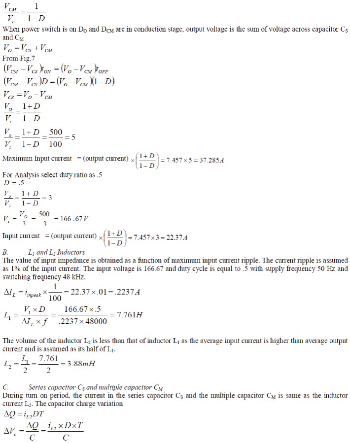
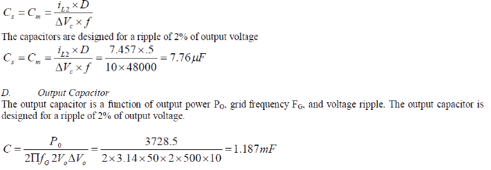
| The design of the 5 HP (3728.5W), 500V, 1720 RPM DC motor is presented in this section. The input voltage is varied between Vi = 100-240V. |
 |
 |
 |
SIMULATION RESULTS
|
| Fig. 8 shows the simulink model of the proposed dc drive. Power factor of the system measured by using the equation |
 |
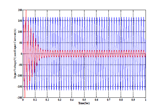
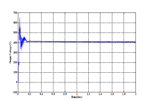
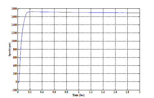
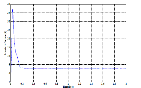
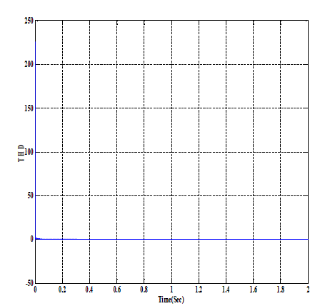
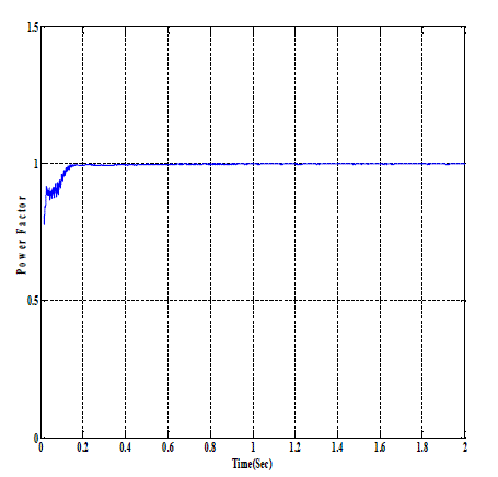
| Fig 9-14 are the output waveforms obtained during simulation. Fig. 9 shows the input voltage and current of the converter. The current is in phase with the voltage which is one of the primary aim. Fig.10, 11 and 12 shows the steady state output voltage, speed of the DC motor and armature current respectively have a fast transient response with a settling time of 0.1 sec. Fig.13 shows THD, which is obtained as .06145. Fig 14 shows the power factor which is obtained as .9976. |
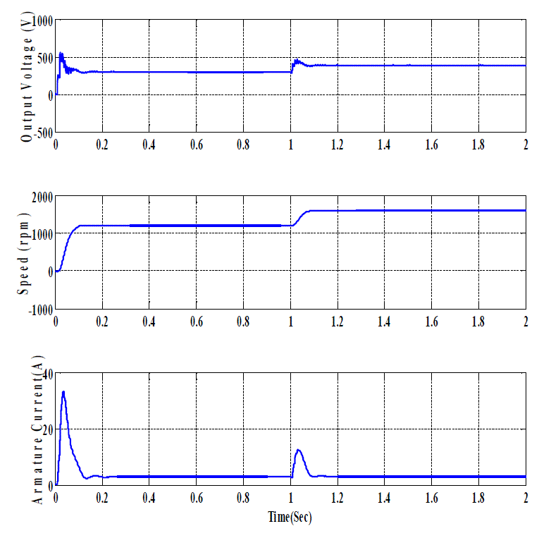
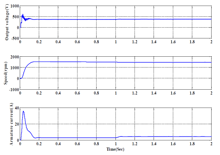
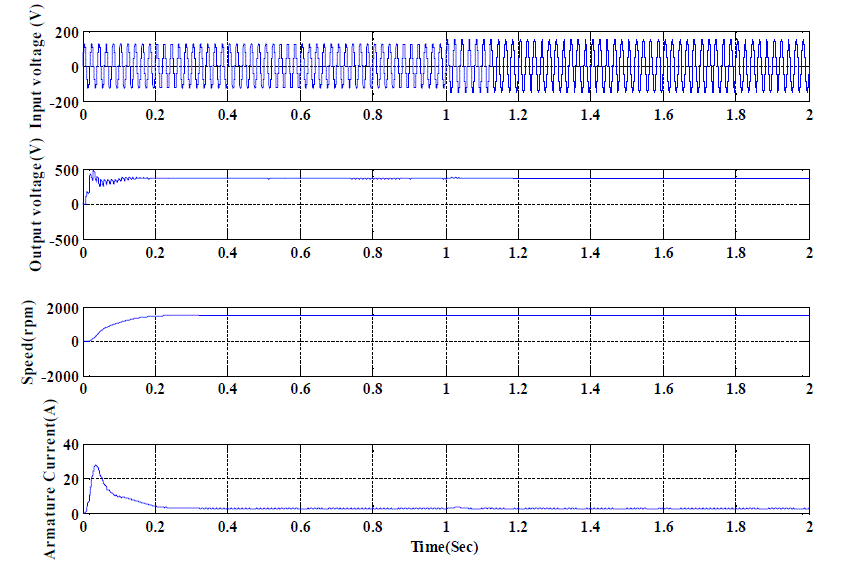
| Fig. 15 shows the response of the system to sudden change in the reference voltage. When speed changes, there will be a corresponding change in the output voltage, but the armature current remains the same. Fig. 16 shows the response of the system to load fluctuations. When there is a load fluctuation, there will be corresponding change in armature current, but the control loop keep the output voltage and the speed as same. Fig. 17 shows the response of the system to the change in input voltage. As it is used for universal input voltage applications, even if there is change in the input voltage, the output voltage, speed and armature current remains same. |
CONCLUSION
|
| Speed control of the DC motor is proposed for universal input voltage applications. The closed loop converter model is simulated on MATLAB simulink. PI controller is used for controlling the speed of the proposed converter. In spite of high circuit complexity the system provide many advantages like high power factor, low total harmonic distortion, and have low diode reverse recovery current. The simulation results of a 5 HP, 500V, 1720 rpm DC motor is evaluated and concluded that the proposed system is suitable for universal input voltage applications and sudden load fluctuations. The main demerits of the proposed converter is that it has higher circuit complexity than the basic converter, also have high switch current stress. It also has high settling time. |
| Stability analysis of system can be done. The system can be modified to control the speed of AC motor by incorporating an additional inverter. It can also be used for variable input voltage application like PV and wind energy system |
Figures at a glance
|
 |
 |
 |
 |
 |
| Figure 1 |
Figure 2 |
Figure 3 |
Figure 4 |
Figure 5 |
 |
 |
 |
 |
 |
| Figure 6 |
Figure 7 |
Figure 8 |
Figure 9 |
Figure 10 |
 |
 |
 |
 |
 |
| Figure 11 |
Figure 12 |
Figure 13 |
Figure 14 |
Figure 15 |
 |
 |
| Figure 16 |
Figure 17 |
|
References
|
- M. Prudente, L. L. Pfitscher, G. Emmendoerfer, E. F. R. Romaneli, and R. Gules, “Voltage multiplier cells applied to non-isolated DC–DCconverters,” IEEE Trans. Power Electron., vol. 23, no. 2, pp. 871–887, Mar.2008.
- P. F.Melo, R.Gules, E. F. R. Romaneli, and R. C.Annunziato, “A modified SEPIC converter for high-power-factor rectifier and universal inputvoltage applications,” IEEE Trans. Power Electron., vol. 25, no. 2, pp. 310–321, Feb. 2010.
- B. Singh, B. N. Singh, A. Chandra, K. Al-Haddad, A. Pandey, and D. P. Kothari, “A review of single-phase improved power quality AC– DCconverters,” IEEE Trans. Ind. Electron., vol. 50, no. 5, pp. 962–981, Oct. 2003.
- J. Qian, F. C. Lee, “A high efficient single stage single switch high power factor ac/dc converter with universal input”, IEEE Trans. PowerElectron., Vol. 13, No. 4, pp. 699–705, 1998.
- C. Qiao, K. M. Smedley, “A topology survey of single-stage power factor corrector with a boost type input current-shaper”, IEEE Trans.Power Electron., Vol. 16, No. 3, pp. 360–368, 2001.
- Q. Zhao, F. C. Lee, “High-efficiency, high step-up DC–DC converters”, IEEE Trans. Power Electron., Vol. 18, No. 1,pp. 65–73, 2003.
- R.J. Wai, R.Y. Duan, “High-efficiency power conversion for low power fuel cell generation system”, IEEE Trans. Power Electron., Vol. 20,No. 4, pp. 847–856, 2005.
|