Keywords
|
| Directional antennas, ad hoc networks, dual sensing, simulation |
INTRODUCTION
|
| In Ad Hoc networks, it is possible to achieve higher throughput using directional antennas as they provide higher antenna gain. Other benefits of the directional antennas include less consumption of transmission power, larger transmission range. Many real time applications are based on the directional antennas. For instance vehicular networks are natural example as the traffic flows in straight line generally. They are also used by Millimeter-wave communications to overcome many path loss problems. Higher spatial reuse is possible when directional antennas are used as they can reduce the blocked nodes in the network. However, MAC protocols that make use of directional antennas face challenges such as exposed terminal, hidden terminal and deafness. They affectthe performance of the network badly. In case of directional antennas, hidden terminals are located nearer to the source node and they are not able to hear transmissions of source node. For this reason they may start transmissions that may case collisions. When a destination does not reply when it is receiving and transmitting in different direction, it is known as deafness problem. When this is not handled, it results in failed transmissions and considered by source node as deafness. There is another problem here that is the source node may also consider the destination node as unreachable. |
| In [1] a dual sensing directional MAC protocol is proposed that makes use of directional antennas to improve the delay performance and throughput in wirelessnetworks. This is achieved by minimizing the undesired effect of deafness, exposed terminal and hidden terminal problems. In order to identify the deafness, the protocol makes use of busy tone signal coupled with the sensing the activity. This avoids the potential blocking problem. Asymmetry-in-gain is the other drawback of existing solutions which is overcome in [1]. Afterwards, the proposed MAC protocol’s integrity is verified using Spin which is nothing but a protocol verification protocol. It also presents a framework for analyzing the delay and throughput in wireless Ad Hoc networks in the presence of directional antennas. The simulation results reveal that the accuracy of the proposed system is more in an order of magnitude. This paper provides the simulated results which prove the efficiency of the proposed protocol. |
| The rest of the paper is organized into some sections. Section II reviews the related work that has been done in literature. Section III provides the proposed model and its advantages. The section IV presents experimental results while the section V concludes this paper. |
RELATED WORK
|
| Wireless ad hoc networks and their protocols attracted many researchers. The research in this area [2], [3] and [4] has focused on the problems of the protocols. In [1] focus is on using directional antenna which is further divided into busy-tone based protocols and non-busy tone based protocols. The following sections present the protocols of both the categories. |
| A.Busy –Tone Based Protocols |
| Literature about busy tone based protocols is in abundance. A DMAC which is tone based is presented in [5]. However, there are many researches [5]-[8]on the MAC protocols of kindbusy tone based. The protocol implemented in [5] uses two channels namely data channel and control channel. The data channel is used to transfer actual data packets while the control channel is only meant for sending a busy tone signal. For every node in the wireless network a unique busy signal is allocated and that can be identified by nodes. Each node should have a hash table to maintain the locations of other nodes in the network. The communication in such networks is described here. When a source node has to send data to destination node, it has to send directional RTS packet towards destination. A directional CTS is the response from the destination. Thus source and destination nodes exchange information in specified directions. When the source node finds a busy tone coming from destination instead of CTS packet, it concludes that situation of deafness and even considers the destination is not reachable. Sometimes there is a chance to miss busy tone signal also. In order to avoid hidden terminal problem, the busy tone signal has to be transmitted along with the RTS packet. The busy tone signal sending from destination to source is proposed in [7] where communication starts with DCTS/DRTS exchange of packets in directional manner. Even a node misses DCTS packet, it results in redundant busy tone. In [8] a protocol by name Dual-Busy-Tone Multiple Access with Directional Antennas(DBTMA/DA) is proposed to accommodatethe network with directional antennas. |
| B.Non-Busy Tone-Based Protocols |
| The earliest protocol of this type is presented in [9] which is based on the new 802.11 MAC protocol. It makes use of per-sector blocking mechanism in order to block any sector when the protocol senses RTS (Request To Send) or CTS(Clear To Send). Omnidirectional fashion is used in [10] to exchange RTS/CTS packets. It takes place after formal protocol handshaking. This protocol is capable of minimizing hidden terminal problem. However, it can’t handle deafness problem and also causes many exposed terminal problems. Multihop RTS MAC protocol is proposed in [11] which make use of directional transmission. Nodes can listen only in omnidirectional mode. However, there exists deafness problem. In [12] a protocol by name Directional Virtual Carrier Sensing is proposed where each node maintains list of neighbors and corresponding directions besides Address of Arrival (AoA) information. It supports basic things of a directional antenna but can’t handle deafness and hidden terminal problems. |
| A circular directional RTS was proposed in [13] and [14] where in each direction RTS has to be transmitted multiple times. Source node location can thus be identified. It is also possible to know the neighbors. Undesired waste of time is reported in these protocols due to their synchronization mechanisms. They also can’t be used for broadcasting and multicasting [6]. This paper presents the implementation of the MAC protocol presented in [1] which overcomes problems of deafness, hidden terminal, and exposed terminal using directional antennas. |
PROBLEM DEFINITION AND SYSTEM MODEL
|
Problem Definition
|
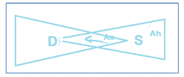
| In the presence of directional antennas, three problems can occur, namely deafness problem, hidden terminal problem and exposed terminal problem. The nodes located within the coverage range of destination node and away from the coverage area of source node are said to be hidden terminals. They can cause degradation of the performance of network. The standard mechanism such as RTS/CTS can’t solve this problem. Further details of this problem can be found in [15]. |
| As can be seen in fig. 1, the area denoted by Ah represents the possible presence of hidden terminals. In case of directional antennas, the exposed terminal problem has to be given more importance. In case of ORTS/OCTS, nodes block sectors unnecessarily thus wasting the change to obtain higher spatial multiplexing gain. |
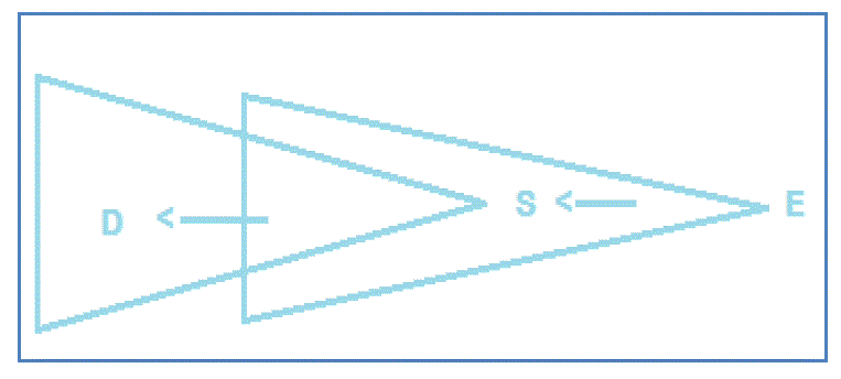
| As can be seen in fig. 2, deafness problems can occur in wireless ad hoc networks when directional antennas are used. When a source node is pointed towards different destination, it fails to communication with the destination node. This problem is named as deafness problem. As seen in fig. 2, the node E is trying to communicate with the node S while it is beamformed towards the node D. The result is that node E tries to transmit data and thus loose energy and even it can conclude that node S is not reachable. |
| In addition to these problems, there is another problem identified. It is known as asymmetry in gain problem. It occurs when there are two types of transmissions that make use of same antenna. As there are different ranges of transmissions simultaneously, it can lead to asymmetry-in-gain problem. The directed signals and omnidirectional radiated signals have transmission ranges that are not identical. The result is that the control packets which are transmitted omnidirectionally can’t reach desired destinations. |
| A.Antenna Model |
| In this paper we assume that the antenna used is having no sidelobes ideally. The area of those sidelobes is much smaller when compared with mainlobes. For this reason the probability of finding wireless nodes within the area of sidelobes is negligible. However, an antenna controller is assumed which keeps track of directions that can provide maximum signal power. In 802.11, the SIFS (Short Interference Space) is defined which is considered long enough for an antenna that is switched between the receiving and transmission modes. Two different sectors are used for data transfer and busy tone signal respectively. |
| B.Busy Tone Signal |
| The model used for busy tone signal is a non-interfering sine-wave which lets other nodes to know the ongoing transmissions. Two patterns are used for this namely ON/OFF pattern and continuous pattern. |
| C.Effect of Mobility on MAC Protocols |
| Mobility does have its effect in wireless ad hoc networks. It may affect both MAC protocols and routing process. When there is mobility, the routing protocols are to deal with change in connectivity while the MAC protocols are affected when time scale of the changes and the time scale of MAC frame are similar. However, the impact of mobility is beyond the scope of this paper. |
| D.DUAL SENSING MAC PROTOCOL WITH DIRECTIONAL ANTENNAS |
| The proposed dual sensing protocol two different wireless channels known as data channel, which is meant for sending data and the control channel, which is meant for controlling the busy tone signal. It makes use of four directions namely DRTS, DCTS, DDATA and DACK. The data channel takes care of CTS, RTS, and ACK beside data packets. |
| E.DRTS/DCTS Communication |
| When a node’s link layers receivepackets from other higher layer, it is capable of sensing it in the specified direction. In the required direction the channel transmits DRTS packets and other directions, it shows a busy tone. When busy tone is sensed by other nodes, they have to postpone DRTS until the busy tone disappears. The receiver node replies to destination node after SIFS period with DCTS packet in a particular direction. Then the BT2 is turned on at all directions. Then the node waits for data packet. As soon as data packet is successfully received it is acknowledged by the destination node by transferring a DACK packet in the same direction. Then its busy-tone signal is turned off. |
| BT1 is used to overcome the problem of hidden-terminal. This is because;the DRTS communication can’t be sensed by the nodes that are located in the hidden terminal area. When they sense BT1, they can avoid initiating a new DRTS. In order to avoid collision, the BT1has to be turned off once DRTS and SIFS are done as the nodes in the hidden terminal area will be able to sense CTS. In the same fashion, BT2 is used to overcome the deafness problem. As specified earlier, this problem occurs when a node is directionally receiving or transmitting data, it will not be able to listen to DRTS. When the source finds a failed DRTS, it is supposed to verify a BT2 from the receiver’s direction else it has to conclude a collision. In case when source node gets DCTS successfully, it can transmit data packet directionally without causing deafness problem. Afterwards, if there is not DACK packet received by source within ACK-timeout period, the transmission is rescheduled thus doubling its back off CW. |
| F.CASE STUDY OF PROPOSED PROTOCOL |
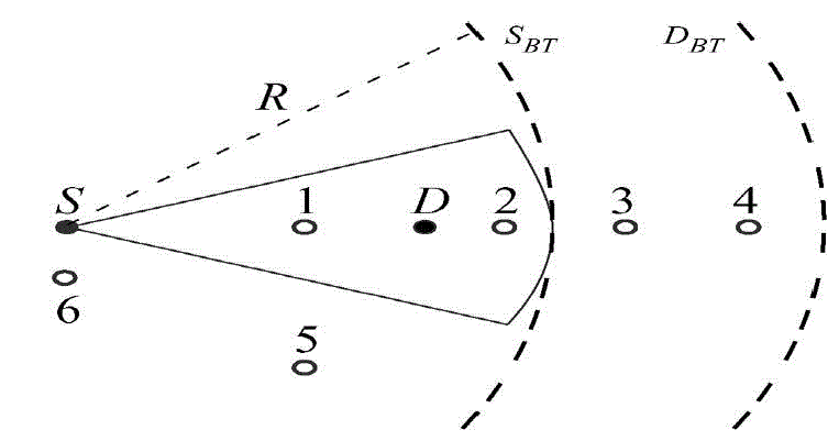
| In order to discuss the design goal of the proposed protocol,a case study network is considered. Fig. 1 shows the case study which illustrates the communication between the source and destination. |
| As can be seen in fig. 3, solid dots are used to denote the source and destination nodes. Nodes 1, 2, 3, and 4 are located on the same line as source and destination are located while the other two nodes i.e. 5 and 6 are positionedat different directions. The dashed curves named SBT and DBT represent the circulation regions of busy tones of nodes S and D respectively. The communication between the source and destination occurs as described here. The source node waits until the nodes 1 and 2 complete their communication mechanism. In the meanwhile it is possible that nodes 3 and 4 can have communication independently as that direction is not blocked. When source node senses no BT1 in the control channel and no data activities in the data channel and its channel towards D is not blocked, it starts communicating with node D. Until node S completes its communication, the node 1 to node 2 communication has to be postponed. Thus based on the above description it is possible for nodes to involve in communication or wait for some time. |
| G.PROTOCOL VALIDATION |
| The validity of proposed MAC protocol is verified using a tool by name SPIN (Simple Promela Interpreter). The tool is used to know whether the newly implemented protocol is capable of solving the problems such as deafness, hidden terminal and exposed terminal in the presence of directional antenna. The SPIN verification results are presented in table 1. |
| As can be seen in table 1, it is evident that the proposed MAC protocol is both blocking free and also deafness free. The results also reveal the fact that transmitting RTS/CTS omnidirectionally in DMAC can block node 5 while nodes 3 or 1 can start communication with node 2. When node 3 misses node 2’s CTS, it also causes deafness problem. In this case MMAC also failed. Tone DMAC is not deafness free while DBTMA/DA is not blocking free. The proposed approach is validated to be deafness free and blocking free. |
EXPERIMENTAL RESULTS
|
| Experiments are made using NS2 simulator. The system parameters used in both the analysis and simulation models are summarized in table 2. |
| As can be seen in table 2, there are many system parameters and their values. These are used for both analytical model and simulation models. |
PERFORMANCE ANALYSIS
|
| This section provides details of analysis with respect to throughput and delay. Analytical models have been developed for both of them. The analysis is based on the following assumptions. |
| • All nodes in the wireless ad hoc network identical having same kind of antennas. |
| • Antenna sectors are associated with each node that can be switched to any direction. |
| • During communication busy tone signal can be communicated through all unused sectors. |
| • Nodes are randomly distributed. |
Throughput and MAC Delay Analysis
|
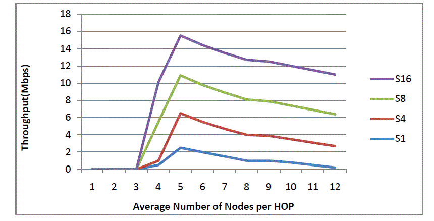
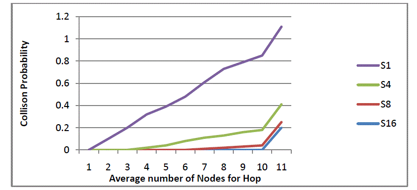
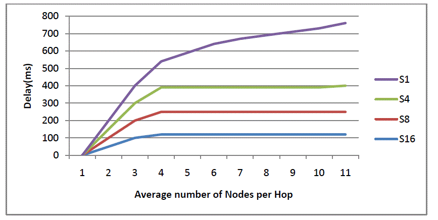
| With respect to analytical model both through and delay analysis are made in [1]. This paper uses the same for its experiments. The graphs presented in this section show the throughput and collision probabilities respectively. |
| As can be seen in fig. 5, it is evident that 1, 4, 8 and 16 antenna sectors are used. The average number of nodes per hop is presented in horizontal axis while the vertical axis presents throughput. |
| As can be seen in fig. 6, it is evident that 1, 4, 8 and 16 antenna sectors are used. The average number of nodes per hop is presented in horizontal axis while the vertical axis presents collision probability. The result reveals that when number of sectors is increased, the collision probability is decreased. |
| As can be seen in fig. 7, it is evident that 1, 4, 8 and 16 antenna sectors are used. The average number of nodes per hop is presented in horizontal axis while the vertical axis presents delay. The delay is reduced when number of sectors is increased. |
CONCLUSION
|
| In this paper we have implemented the MAC protocol based on dual sensing strategy using NS2 simulator. The implemented protocol is meant for wireless multihop ad hoc networks. The network makes use of directional antennas. The existing protocols were able to use directional antennas but unable to handle problems such as deafness, exposed terminal and hidden terminal. The proposed implementation overcomes these problems based on the dual sensing strategy. Afterwards, the Spin tool is used to verify the integrity of the protocol. The simulation results are compatible with analytical model presented in this paper. The proposed MAC protocol is capable of improving the performance of wireless networks by using directional antennas. |
Tables at a glance
|
 |
 |
| Table 1 |
Table 2 |
|
Figures at a glance
|
 |
 |
 |
| Figure 1 |
Figure 2 |
Figure 3 |
 |
 |
 |
| Figure 4 |
Figure 5 |
Figure 6 |
|
References
|
- Ahmad Ali Abdullah, Member, IEEE, Lin Cai, Senior Member, IEEE, and Fayez Gebali, Senior Member, IEEE, “DSDMAC: Dual SensingDirectional MAC Protocol for Ad Hoc Networks with Directional Antennas”. IEEE TRANSACTIONS ON VEHICULAR TECHNOLOGY, VOL. 61, NO.3, MARCH 2012.
- G. Bianchi, “Performance analysis of the IEEE 802.11 distributed coordination function,” IEEE J. Select. Areas Commun., vol. 18, no. 3, pp.535– 547, Mar. 2000.
- L. X. Cai, L. Cai, X. Shen, J. Mark, and Q. Zhang, “MAC protocol design and optimization for multihop ultra-wideband networks,” IEEETrans.WirelessCommun., vol. 8, no. 8, pp. 4056–4065, Aug. 2009.
- J. Chen, Q. Yu, P. Cheng, Y. Sun, Y. Fan, and X. Shen, “Game theoretical approach for channel allocation in wireless sensor and actuatornetworks,” IEEE Trans. Autom. Control, vol. 56, no. 10, pp. 2332–2344, Oct. 2011.
- R. R. Choudhury and N. H. Vaidya, “Deafness: AMAC problem in ad hoc networks when using directional antennas,” in Proc. IEEE ICNP,2004, pp. 283–292.
- Q. He, L. Cai, X. Shen, and P. H. Ho, “Improving TCP performance over wireless ad hoc networks with busy tone assisted scheme,” EURASIP J.WirelessCommun. Netw., vol. 2006, no. 2, pp. 1–11, Apr. 2006.
- S. S. Kulkarni and C. Rosenberg, “DBSMA: A MAC protocol for multihopad-hoc networks with directional antennas,” in Proc. IEEE PIMRC, Sep. 2005, vol. 2, pp. 1371–1377.
- Z. Huang, C. C. Shen, C. Srisathapornphat, and C. Jaikaeo, “A busy-tone based directional MAC protocol for ad hoc networks,” in Proc.IEEEMilcom, 2002, pp. 1233–1238.
- Y. B. Ko, V. Shankarkumar, and N. H.Vaidya, “Medium access control protocols using directional antennas in ad hoc networks,” in Proc.IEEEINFOCOM, Mar. 2000, vol. 1, pp. 13–21.
- Nasipuri, S. Ye, J. You, and R. Hiromoto, “A MAC protocol for mobile ad hoc networks using directional antennas,” in Proc. IEEE WCNC, Sep. 2000, vol. 3, pp. 1214–1219.
- R. R. Choudhury, X. Yang, N. H. Vaidya, and R. Ramanathan, “Using directional antennas for medium access control in ad hoc networks,” in Proc. ACM MobiCom, 2002, pp. 59–70.
- M. Takai, J. Martin, A. Ren, and R. Bagrodia, “Directional virtual carrier sensing for directional antennas inmobile ad hoc networks,” in Proc. ACMMobihoc, 2002, pp. 183–193.
- E. Shihab, L. Cai, and J. Pan, “A distributed, asynchronous directionalto- directional MAC protocol for wireless ad hoc networks,” IEEETrans.Veh. Technol., vol. 58, no. 9, pp. 5124–5134, Nov. 2009.
- T. Korakis, G. Jakllari, and L. Tassiulas, “A MAC protocol for full exploitation of directional antennas in ad-hoc wireless networks,” inProc.ACMMobiHoc, 2003, pp. 98–107.
- Abdullah, F. Gebali, and L. Cai, “Modeling the throughput and delay in wireless multihop ad-hoc networks,” in Proc. IEEE GLOBECOM, 2009, pp. 1–6.
|