Keywords
|
| Harmonic Distortion, Optimization, Passive Filters, Power Quality, Economics. |
INTRODUCTION
|
| Electrical power generation, transmission and utilization theories are designed to function at the fundamental industrial frequency which is 50 or 60 Hz. In power distribution networks, nonlinear loads produce harmonic currents that can pass through other sensitive locations in the power system and eventually back to the source. Harmonic currents can produce a variety of effects that are harmful to a power system structure. Harmonic currents are a result of the nature and characteristics of these loads. As long as we have to employ those loads in all the industrial commercial and residential sectors, we have to deal with the reality that harmonic currents will exist to a degree dependent upon the loads. The degrees and magnitudes of the harmonics created by the nonlinear loads are function of the load design and the interaction of the nonlinear load with the distribution system impedance [1]-[6]. |
| In this paper, the recently introduced C-type passive filter is presented for reducing harmonics distortion and improving the load true power factor based on minimization of the total investment cost of the proposed filter under nonsinusoidal conditions. In this paper, optimal sizing of C-type passive filter parameters is presented based on minimization of its total investment cost under non-sinusoidal conditions, while taking into consideration the following constraints [7]: Maintaining the load power factor (PF) at an adequate range, i.e. 90%≤ PF ≤ 95%. Maintaining the voltage total harmonic distortion (THDV) at an acceptable range according to the system voltage level, i.e. THDV ≤ 5%. Maintaining the current total demand distortion (TDD) at an acceptable range, i.e. TDD ≤ max %TDD. The maximum %TDD is determined according to the system strength as clarified in [3]. Maintaining the individual harmonics of the voltage and current measured at the point of common coupling between the utility and the consumer at their specified ranges according to the limitations given in IEEE standard 519-1992 [3]. Maintaining the shunt power capacitor loading duties at their specified ranges according to IEEE Standard 18-2002 [8]. |
| The paper is divided to seven sections as follows: Section II is a literature survey, Section III describes the configuration of the C-type filters; Section IV presents the mathematical modelling of the system under study. Section V presents the formulation of the optimization problem. Section VI shows the results and their discussion. Section VII is dedicated for conclusions of this study. |
LITERATURE SURVEY
|
| Different researchers have studied the proper limitation of harmonic disturbance levels, and among several techniques used to reduce these harmonic disturbances, the most frequently employed are the passive filters, due to their simplicity and economical cost [9]-[14]. Passive filters have many types that can achieve different frequency response characteristics. In the literature, C-type filters have three advantages more than conventional passive filters. Firstly, Ctype filters have low fundamental frequency power loss compared to other types of the filters; hence they are considered energy efficient passive filters. Secondly, they can damp resonance that may occur with the utility system. Thirdly, C- type filters are considered low cost filters that can serve well as low or high passive filters [5]. Accordingly, many studies present the C-type filter as a reasonable passive solution. The C-type filter combined with an active filter for cost-effective compensation was considered in [12], with the aim to minimize the power rating of the active filter by optimizing parameters of the C-type filter using the grid search method as the optimization method. Additionally, optimal sizing of the parameters of the C-type passive filter for minimizing total voltage harmonic distortion using FFSQP (FORTRAN feasible sequential quadratic programming) was presented in [1]. Recently, three C-type filter design studies [13], [7], [14] are presented for the effective utilization of cables and transformers under non-sinusoidal conditions, maximization of the load power factor, and maximization of the loading capabilities of the transformers supplying non-linear loads, respectively. |
CONFIGURATION OF THE C-TYPE FILTER
|
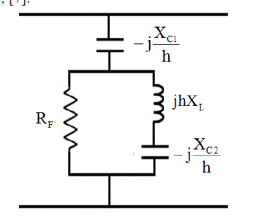
| C-type passive filters (CPF) are an alternative method for low-pass broadband filters in reducing multiple harmonic frequencies simultaneously. The configuration of a C-type filter is similar to the second-order high-pass filter [5]. The main distinction between the two configurations is that the C-type filter possesses an auxiliary capacitor C2 in series with the inductor L. A typical configuration of a C-type filter is shown in Fig. 1. The auxiliary capacitor C2 is sized in such a way that its capacitive reactance (-jXC2/h) cancels out the inductive reactance (jhXL) at the fundamental frequency, where h is the harmonic number presented. Thus, bypassing the damping resistance RF will occur. For this reason, the losses associated with RF are practically eliminated allowing the CPF to be tuned to a low frequency. This situation cannot be achieved with the conventional second-order high-pass passive filters. The proposed CPF acts as a standalone capacitor C1 connected to the distorted load bus at the fundamental frequency that provides the system by the reactive power needed for improving the load true power factor. As frequency increases; the capacitive reactance of C2 decreases and the inductive reactance of L increases. Therefore, impedance of the series L and C2 branch is dominated by the inductive reactance of L, i.e. (hXL). The high-frequency response of the CPF and that of the secondorder high-pass filter are similar [4], [5], [7]. |
| The hth harmonic impedance of the C-type filter, ZCh, can be defined as follows: |
 (1) (1) |
| The series capacitor-inductor (C2-L) branch is tuned to the fundamental frequency, so that (-jXC2+jXL) will be equal. Thus one can define the following: |
 (2) (2) |
| The main capacitive reactance of the C-type filter (XC1) can be determined according to the voltage level of the load and amount of the reactive power (QC1) needed to achieve the desired value of the displacement power factor (dPF) as follows, where P1 is the fundamental load active power and VS1 is the fundamental value of the background supply voltage. It must be noted that the capacitor's nominal voltage is assumed to be equal to the fundamental source voltage VS1 to avoid the capacitor loading [10]. |
 (3) (3) |
| The hth harmonic reactance of XL-C is related to XC1 by the tuning harmonic number, h*. At h*, imaginary part of the Ctype filter's impedance can be approximated and given as follows: |
 |
| Thus, the fundamental value of the reactance XL-C can be defined as: |
 (5) (5) |
| In simple words, the range of variability of the reactance (XL-C) is chosen based on the lower and upper acceptable boundaries of the tuning harmonic order (h*). Finally, one can determine the range of variability of the parallel resistance RF according to quality factor (q) of the the C-type filter, as follows: |
 (6) (6) |
| Consequentially, the optimal sizing of filter’s parameters can be defined to be the optimal choice of the parameters: XC1, h* and q in order to meet the desired system performance with the power quality indices stated in IEEE Standard 519-1992 [3]. |
MATHEMATICAL MODELLING OF THE SYSTEM UNDER STUDY
|
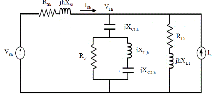
| Let us assume that the proposed C-type filter is installed at a distorted load bus whose harmonic voltage is denoted as VLh where linear and nonlinear loads are connected. Generally, nonlinear loads or harmonic sources are considered as injection sources into the linear network models. Usually, the voltage distortion at the service bus is relatively low; thus the current distortion for many nonlinear types is relatively constant and independent of the voltage distortion in the supply system. Accordingly, nonlinear loads can be represented by constant current source models. The utility side is represented as the Thevenin equivalent voltage source VSh and the Thevenin equivalent impedance ZSh which is seen from the load point of view. Additionally, voltage source nonlinearity is represented in the source harmonic voltages as VSh. Fig. 2 shows the single-phase equivalent circuit of the system configuration under study, where it is considered as a balanced system. RL1 and XL1 are the magnitudes of load resistance and reactance, respectively, also, RS1 and XS1 are the magnitudes of the source resistance and reactance, all expressed in ohms at the fundamental frequency. The hth harmonic impedances of the source and the load are given in (7) and (8), respectively. |
 (7) and (8) (7) and (8) |
| Regarding the skin effect, the Thevenin source impedance is represented as follows [13]: |
 (9) (9) |
| Recalling [13], and using the superposition theorem; the hth harmonic supply current ISh can be given as follows: |
 (10) (10) |
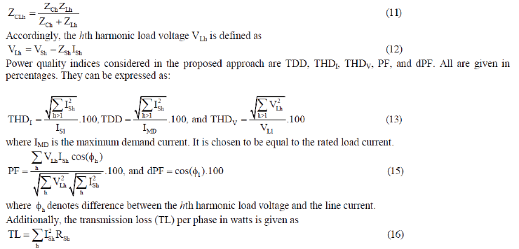
| where ZCLh is the parallel combination of ZCh and ZLh. It is given as |
 |
| Hence, formulation of the optimization problem of the proposed C-type passive filter will be solved for the system under consideration. |
FORMULATION OF THE OPTIMIZATION PROBLEM
|
| In this scheme, objective function will be primarily derived. Hence, constraints of the optimization problem will be presented. Finally, quick notes about the optimization method will be demonstrated. |
| A. Objective function |
| The goal of the optimization process is to find out the optimal sizing of the proposed filter parameters which achieve minimum investment cost. In the design procedure, there are four parameters of the C-type filter (C1, C2, L, and RF) which have been introduced using the three variables (XC1, h*, and q) as shown in Equations (3)-(6). Hence, these parameters will be varied until the global or near global objective function is achieved with a suitable tolerance. The total investment cost (Cost) of the proposed C-type filter is defined as the summation of the cost of all its components. It is given as follows: |
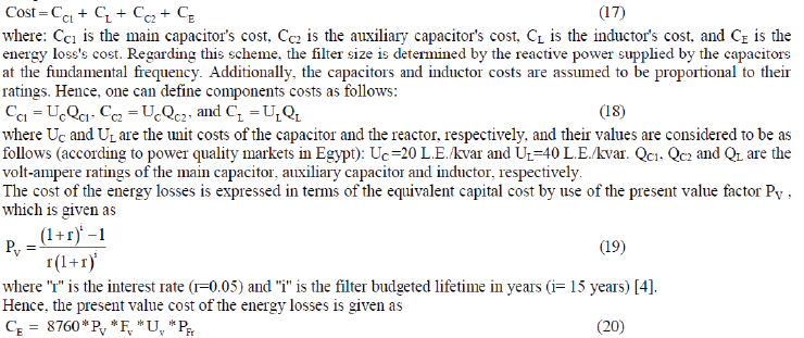 |
| where: FV is the filter utilization factor (FV=1), UV is the cost of power loss per kilowatt hours (Uv =0.365 L.E./kWhr) and PFr is the filter power losses per phase in watts. |
| B. Formulation of the constraints |
| According to IEEE 519–1992 [3], %THDV for voltage level up to 69 kV is less than or equal to 5.0%. Each individual harmonic voltage is limited to 3%. %TDD should be limited to a standard percent according to the ratio between the system short-circuit current and the load current. The shunt capacitor will be capable of continuous operation, provided that none of the following limitations are exceeded [8]: 135% of nominal rms current based on rated kVA and rated voltage, 110% of rated rms voltage, 120% of rated peak voltage, and 135% of nameplate kvar. Beside, maintaining the values of displacement power factor dPF and the load power factor PF within an acceptable specified range (≥ 90%) is desired. Thus, the objective function for the proposed filter, complying with the previous constraints, is presented as: Minimize Cost (XC1, h*, and q), subjected to the previous constraints. |
| C. Optimization method |
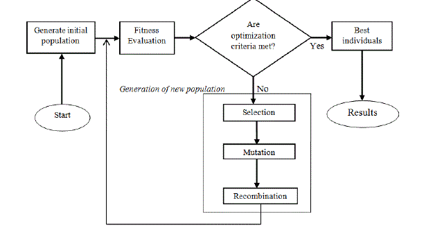
| Regarding solving the optimization problem presented in the previous section; the Genetic Algorithm toolbox is chosen. In the literature [15]- [17], GA is a search mechanism based on the principle of natural selection and population genetics. An increasingly better approximation of the desired solution can be produced by applying the principal of survival of the fittest. In each generation, a new set of approximations of the solution are chosen according to the fitness evaluation. Thus, population of solutions is improved from one generation to the next with respect to their fitness evaluation. The least fit individuals are replaced with new offspring, which come from a previous generation and which are better suited to the evolution of the environment. The more fitness has, the more chance of be selected. The algorithms will repeat until a termination condition is satisfied. The best solution is returned to represent the optimum (global) solution. Fig. 3. shows a general flow chart for the evolution nature of the GA. In this study, GA as an optimization method has been chosen among many optimization methods because the genetic algorithm method is one of few that has the following advantages [15], [16]: |
| Can be employed with continuous or discrete variables. Does not require derivative information. Can be employed with a large number of variables. It is well-suited for parallel computers. Can be employed with numerical generated data, experimental data, or analytical functions. |
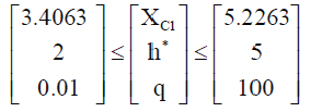
| In this study, the lower and upper boundaries of the main capacitive reactance (XC1) are selected as the reactance values of a direct stand-alone capacitor that improve the load’s actual displacement power factor from its low value (0.7165) to an acceptable range, i.e. dPF ≥ 0.95. The lower and upper boundaries of the tuning harmonic order (h*) is considered between 2 and 5, this is because the proposed C-type filter is employed as a low-pass filter. The range of variability of the filter's quality factor is chosen between 0.01 to 100. Equation (21) shows numerical values of the bounds of variables of the optimization problem. |
 |
| Additional specifications of the search algorithm of the GA's toolbox can be summarized as follows: |
| Population size = 20 individuals. Crossover probability = 0.8. Mutation probability = 0.01. Termination condition is 100 generations. Selection: Using Roulette-wheel technique. Cross-over: Shuffling crossover [7], [17]. |
RESULTS AND THEIR DISCUSSION
|
| Four cases of a typical industrial plant were simulated using the GA optimization method. The numerical data were taken from an example in IEEE Standard 519-1992 [3]. The inductive three-phase load is 5100 kW and 4965 kvar with a dPF of 0.7165. The 60-cycle supply bus voltage is 4.165 kV. Table 1 shows the detailed specifications of the system under study, background harmonic voltage components and the injected harmonic current components. |
| Table 2 shows the uncompensated system parameter results in order to be compared with the compensated system results. |
| Table 3 shows the compensated system results with the proposed C-type passive filter. Comparing the results presented in Tables 2 and 3, it is notable that the general improvement in the system performance after adding the proposed Ctype filters for all cases under study. The resultant percentages of the considered power quality indices (THDv, THDI, TDD, PF and dPF) are all within their acceptable ranges. Additionally, Table 3 shows that the presented method results in lower supply current and thus lower transmission losses than the uncompensated case shown in Table 2. So, the main advantage of the presented method consists of less harmonic distortion which lead to much higher power quality of all the connected equipments. This is usually helpful for assuring efficient and reliable power distribution systems. |
| Table 4 shows the detailed specifications of the proposed filters. As shown in Table 3, for equal short-circuit capacity systems, the additional supply voltage harmonic contents for the same harmonic load will result in a lower load power factor because of the increase of the current flowing through the compensated load, as well as increased total current and voltage distortion percentages. Additionally, an increase in the transmission power losses will be observed. Therefore, the transmission efficiency will decrease which will reflect on the investment cost of the proposed filter as shown in Table 4. |
| Higher short-circuit capacity systems with the same harmonic levels corresponds to higher total current harmonic distortion. This is expected due to the lower Thevenin impedance, so higher harmonic current will flow into the compensated load. This will lead to higher investment cost of the proposed filter as shown in Table 4 [1]. |
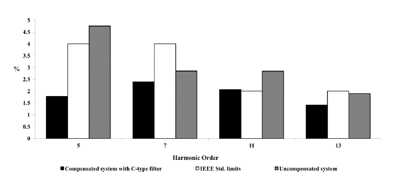
| Fig. 4 shows the individual harmonic components of the supply current, before and after compensation for the system under study, Case 2. It is notable that all of the individual harmonic currents components have met the IEEE Standard 519 limits. |
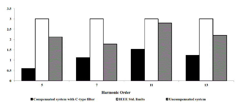
| Fig. 5 shows the individual harmonic components of the voltage measured at the point of common coupling (PCC), before and after compensation. It is notable that the presented filter maintains an allowable voltage quality, since all the individual harmonic voltage components are complying with the standard limits. |
| Based on the results gained from this study, the investment cost of the C-type filter is cheaper than the conventional shunt passive filter when the energy loss cost is included because of its lower fundamental power loss, and certainly cheaper than the second-order passive filter that suffer from extra power losses when tuned to a low frequency. In other words, for the presented filter: Case 3, the power loss of the C-type filter (per phase) is equal to 0.22 kW with a total investment cost of 33.2393 thousands L.E., while for a traditional shunt filter designed under the same conditions, the corresponding filter power loss will be 4.07 kW, which means that its investment cost will be almost three times more than the C-type filter. For a second order filter designed under the same operating conditions, it will suffer from a very high power losses (approximately 1316 kW), which will lead to a very high investment cost. |
| These results clarify that the proposed C-type filter provides very low power loss compared to other passive filter configurations. Accordingly, demonstrate the reason of the advance in C-type passive filter use in the industrial plants. |
CONCLUSION
|
| This paper presents an application of the Genetic Algorithm toolbox (GA) provided by MatLab software in order to find the optimal sizing of parameters of C-type passive filters based on minimization of the total investment cost of the proposed filters under non-sinusoidal conditions. Numerical results clearly show the great merits of the proposed Ctype passive filters employed in the industrial plants. It was obvious that the C-type passive filter can work efficiently as a low-pass filter and mitigates low-order harmonics with a good harmonic attenuation at its tuned frequency. Economic assessment of the proposed C-type passive filters and other conventional passive filters topologies show the economical merits of using the proposed filter. Accordingly, it can be introduced as an energy efficient passive filters in the power distribution networks. |
Tables at a glance
|
 |
 |
 |
 |
| Table 1 |
Table 2 |
Table 3 |
Table 4 |
|
Figures at a glance
|
 |
 |
 |
 |
 |
| Figure 1 |
Figure 2 |
Figure 3 |
Figure 4 |
Figure 5 |
|
References
|
- S. H. E. Abdel Aleem, A. F. Zobaa, and M. M. Abdel Aziz, “Optimal C-Type Passive Filter Based on Minimization of the Voltage HarmonicDistortion for Nonlinear Loads,” IEEE Transactions on Industrial Electronics, vol. 59, no. 1, pp. 281–289, Jan. 2012.
- M. M. Swamy, Passive techniques for reducing input current harmonics. Yaskawa Electrical America. [Online]. Available:http://www.controldesign.com/assets/13WPpdf/1306-yaskawa-input-current-harmonics.
- IEEE Recommended Practices and Requirements for Harmonic Control in Electrical Power Systems, IEEE Standard 519–1992, 1992.
- M. Z. El-Sadek. Power Systems Harmonic Filters. 1st ed., Muktar Press, Assiut, Egypt, 2007.
- R. C. Dugan, M. F. M. Granaghan, S. Santoso and H. W. Beaty. Electric Power Systems Quality. New York: McGraw-Hill, 2002.
- S. H. E. Abdel Aleem, M. T. El-Mathana, and A. F. Zobaa, “Different Design Approaches of Shunt Passive Harmonic Filters Based on IEEEStd. 519-1992 and IEEE Std. 18-2002,” Recent Pat. Elec. Eng., vol. 6, no. 1, pp. 68-75, Jan. 2013.
- F. Mohamed, S. H.E. Abdel Aleem, A. M. Ibrahim, and A. F. Zobaa, “Optimal Sizing of C-type Passive Filters under Non-sinusoidalConditions,” Energy Technology & Policy, vol. 1, no. 1, pp. 1–10, Aug. 2014.
- IEEE Standard for Shunt Power Capacitors, IEEE Standard 18-2002, 2002.
- S. H. E. Abdel Aleem, A. F. Zobaa, and A. C. M. Sung, “On the economical design of multiple-arm passive harmonic filters,” in 47thInternational Universities' Power Engineering. Conf., UPEC’12, Uxbridge, Middlesex, United Kingdom, Sep. 4–7, 2012, pp. 1–6.
- F. Zobaa and S. H. E. Abdel Aleem, “A New Approach for Harmonic Distortion Minimization in Power Systems Supplying NonlinearLoads,” IEEE Transactions on Industrial Informatics, vol. 10, vo. 2, pp. 1401–1412, May 2014.
- M. M. Abdel Aziz, E. E. Abou El-Zahab, and A. F. Zobaa, “LC compensators based on cost minimization for nonlinear loads,” 2003 LargeEngineering Systems Conf. Power Engineering, LESCOPE’03, Montreal, Quebec, Canada, May 7–9, 2003, pp. 143–147.
- Q. Chen, Z. Chen, M. McCormick, and A. Dinu, “The Application and Optimization of C-type Filter in a Combined Harmonic Power Filter,”in 35th IEEE Power Electronics Specialists, PESC 2004, Aachen, Germany, Jun. 20–25, 2004, pp. 1041–1045.
- S. H. E. Abdel Aleem, M.E. Balci, A. F. Zobaa, and S. Sakar, “Optimal passive filter design for effective utilization of cables and transformersunder non-sinusoidal conditions”, Proc. of 16th Int. Conf. Harmonics and Quality of Power, ICHQP’14, Bucharest, Romania, May 25–28,pp. 626–630, 2014.
- M. E. Balci, “Optimal C-Type Filter Design to Maximize Transformer's Loading Capability under Non-sinusoidal Conditions”, Electric PowerComponents and Systems, vol. 42, no. 14, pp. 1565-1575, Sep. 2014.
- H. Pohlheim. Evolutionary Algorithms. Springer, Heidelberg, 2003.
- R. L. Haupt, and S. E. Haupt. Practical genetic algorithms. 2nd ed., John Wiley & Sons Inc., Hoboken, New Jersey, 2004.
- P. Zacharia, A. Menti, and T. Zacharias, “Genetic algorithm based optimal design of shunt compensators in the presence of harmonics”,Electr. Power Syst. Res., vol. 78, no. 4, pp. 728–735, April 2008.
|