Keywords
|
| PID controller, Internal Model control (IMC), Ziegler-Nichols (Z-N) and Level process. |
INTRODUCTION
|
| The level control is mainly used for industrial process application. Researchers have also brought out the idea of level control for non-linear processes[5],[6],[7],[8],[9]. The general objective of the level process is to achieve a set point and stabilize the level in a cylindrical tank Manufacturers may use one of many different measurement technologies to determine level, including radar, ultrasonic, float gauge, and pressure measurement. Cylindrical tank system relates to liquid level control problems generally existing in industrial surge tanks .The final control element in a level control loop is usually a valve on the input and/or outflow connections to the tank. Because it is often critical to avoid tank overflow, redundant level control systems are sometimes employed. The final product always depends on the accuracy of the level controller. The purpose of controller is to attain the target and capable of tracking a new set point values quickly. Controllers are tuned in an effort to match the characteristics of the control equipment to the process and to maintain the system stable. The tuning methods (Z-N and IMC) are used to tune the controllers in the level process. Some researchers have interfaced a transducer with non-linear process using simulated annealing.[6] |
| The Internal Model Control (IMC) structure provides a suitable framework for satisfying these objectives. A detailed description about the Internal ModelControl(IMC)was given by Morari and Zafiriou[2], and this technique was used by a number of other researchers. Using the Internal ModelControl (IMC) design procedure, controller complexity depends exclusively on two factors: the complexity of the model and the performance requirements stated by the designer. The goal of this article is to show that for the objectives and simple models common to chemical process control, the IMC design procedure leads naturally to PID-type controller. |
MATERIALS
|
| A. Experimental setup |
| The experimental setup consists of a cylindrical tank, a water reservoir, pump, Rota meter, and a differential pressure transmitter, a current to pressure converter (I /P converter), a pneumatic control valve, and a personal computer (PC).The pressure difference is calculated using Differential Pressure Transmitter .It also senses the current signal and sends it to the display box. |
| The current to pressure converter converts the current signal (4-20mA) to pressure signal (3-15psi).The control valve is used to adjust the flow. The purpose of Level Transmitter is to sense the level and produce an output current. |
| B. Technical Details |
| The experimental setup consists of the following specifications. |
PROCESS IDENTIFICATION
|
| The process is identified by the Step Test method[3]. This phenomenon was developed by Ziegler and Nichols [1] and is commonly known as “Process Reaction” or “Transient Response” method. The basic approach is to open the feedback loop, so that no control action occurs. Initially the process is set at manual mode and step test is performed by varying the inflow rate.The open loop step response is obtained and the transfer function for the Process Reaction method[1] is framed. |
| A. Steps To Obtain Transfer Function: |
| The controller is placed in manual mode and waited for the process to reach the settling state. An initial step change is given in the flow and checked till the process variable (PV) settles out at a new value. |
| The process gain is calculated as follows, |
| Process gain (K) =Change in process value/Change in input value |
| B. Measurement of Dead Time (θ): |
| Dead time is the amount of time taken by the process variable to first respond after the change in input. |
| C. Measurement of Time Constant (τ): |
| τ =time difference between the dead time and Process variable reaching 63.2% of its total change.The value of the Process Variable at 63.2% (0.632) of its final value is taken as time constant. |
| D. General format of a transfer function: |
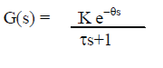 |
| E. Transfer Function Obtained: |
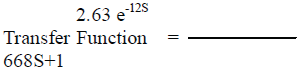 |
CONTROLLER DESIGN
|
| A. Ziegler-Nichols Controller (Z-N): |
| Ziegler and Nichols [1] or Ultimate Gain method is based on adjusting a closed loop until steady oscillations occurs. The integral and derivative time is kept at zero and the proportional gain is varied by “trial and error” method till the sustained oscillations are obtained. The ZN controller parameters are obtained from the formulae in Table 2. |
| B. Internal Model Controller (IMC) |
| Internal Model Control (IMC) [4] is distinct for single input-single output discrete time systems and its interaction with other control schemes are recognized. The IMC structure provides a practical tool to influence dynamic performance and strength to modelling errors in the design. PI- and PID-tuning rules for systems modelled by a first-order lag with dead time are derived analytically. The superiority of these rules in terms of both closed-loop performance and robustness is demonstrated. The IMC controller parameters are obtained by using the formulae below (Table 3). |
RESULTS AND DISCUSSION
|
| The controller parameters are therefore calculated and listed in Table 4 and Z-N and IMC controllers were tuned using them .The models of controllers were compared in Fig.3 .The best among the two isfound. |
| The graph (time vs. level) was plotted for level process. It clearly sights the curves of two controllers (Z-N and IMC). The comparison between two curves is done and the best one will be highlighted. |
CONCLUSION
|
| The obtained results confirmed that the IMC based PI controller yield better results than ZN method. The simulation responses for the models validated reveals the efficiency of the IMC based PID controller in provision of time domain specifications by achieving minimum settling time and no overshoot. Hence from the above results it is concluded that IMC seems to be an improved choice for the Liquid level control of process tank than conventional PI controllers. |
Tables at a glance
|
 |
|
|
|
|
| Table 1 |
Table 2 |
Table 3 |
Table 4 |
Table 5 |
|
Figures at a glance
|
 |
 |
 |
| Figure 1 |
Figure 2 |
Figure 3 |
|
References
|
- G.Ziegler and Nicholas,”Optimum Settings for Automatic controllers”,Trans.Asme,62,1942,pp.759-768.
- M. Morari and E.Zafiriou, Robust Process Control, Englewood cliffs, prentice-Hall, 1989.
- Donald R. Coughanowar, Process System Analysis and Control, Second Edition, Tata McGraw Hill, 1991.
- B.WayneBequette, Process Control: Modelling, Design and Simulation, Prentice Hall (2003) of India.
- J.Prakash, K.Srinivasan,”Design of Non Linear PID Controller and Non Linear Model Predictive Controller for a Continuous stirred tankReactor”, ISA Transactions 48(2009)273_282.
- S.M. Girirajkumar, K.Ramkumar, Bodlarakesh, Sanjay Sarma O.V. and Deepak Jayaraj,”Real Time Interfacing of a Transducer with a Non-Linear Process Using Simulated Annealing”, Sensors and Transducers Journal, Vol.121,Issue 10, October 2010, Pp.:29-4.1
- V.R.Ravi, T.Thyagarajan,”Application of Adaptive Control Technique to interfacing Non Linear systems” Electronics ComputerTechnology(ICECT),2011 3rd International Conference on 8-10 April 2011, Pp.:386-392.
- P.Aravind, M.Valluvan and M.Saranya,”Simulation Based Modelling and Implementation of Adaptive Control Technique for NonlinearProcess Tank” International Journal for Computer Applications, Entitled Volume68,No.16,April 2013.
- P.Aravind, M.Valluvan and S.Ranganathan “Modeling and Simulation of Non Linear Tank” International Journal of Advanced Research inElectrical, Electronics and Instrumentation EngineeringVol. 2, Issue 2, February 2013.
|