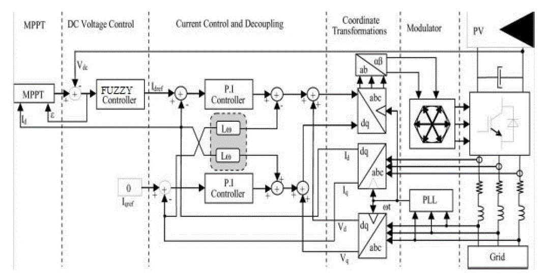
A Modified MPPT-SRF Configuration of a Single Stag Grid-Connected PV System Inverter Based On Voltage-Oriented Control is shows better performance in conversion of PV output power into high-quality ac voltage. Hear the purpose of voltage-oriented control (VOC) is to solve fast varying irradiation problems. In VOC, a cascaded control structure with an outer dc link voltage control loop and an inner current control loop is used. The currents are controlled in a synchronous orthogonal d-q frame using a decoupled feedback control. The reference current of proportional–integral (PI) d-axis controller is replaced with FUZZY controller to improve the fastness of the triggering circuit of the VSI. With this we can achieve a unity power factor, the q-axis reference is set to zero and wave distortion are reduced which gives an improved efficiency. Simulations and experimental results demonstrate that the proposed method provides effective, fast, and perfect tracking. The results are examined by using MATLAB software.
INTRODUCTION |
| The voltage-power characteristic of a photovoltaic (PV) array is nonlinear and time varying because of
the changes
caused by the atmospheric conditions. The task of a maximum power point (MPP) tracking (MPPT) in a PV
power
system is to continuously tune the system so that it draws maximum power from the PV array.In recent
years, the grid
connected PV systems have become more popular because they do not need battery backups to ensure MPPT.
The two
typical configurations of a grid-connected PV system are single or two stages. In two stages, the first
is used to boost
the PV array voltage and track the maximum power; the second allows the conversion of this power into
high-quality
ac voltage. |
| The presence of several power stages undermines the overall efficiency, reliability, and compactness
of the system
besides increasing the cost. The single stage has numerous advantages, such as simple topology, high
efficiency, etc.
Nevertheless, the control strategy (FZZY Logic) has to be designed in order to extract the maximum
available power
and to properly transfer it from the PV array to the grid simultaneously. In this case, an important
consideration in the
controller design is needed. |
| In this paper, the main component of the single-stage grid connected PV system is the three-phase
voltage source
inverter (VSI). Typically, simple inductors L are used as a filter interfacing inverter and mains, as
shown in Fig. 1. LCL
filter provides advantages in costs and dynamics since smaller inductors can be used. However, in a
grid-connected
system, an LCL filter may cause resonance, which is a disaster for the system’s stability. Hence,
control systems
involving LCL filters are inevitably more complicated. The voltage-oriented control (VOC) method used
for VSI
employs an outer dc link voltage control loop and an inner current control loop to achieve fast dynamic
response. The
performance of the power flow depends largely on the quality of the applied current control strategy. In
this paper, the
current control has been implemented in a rotating synchronous reference frame d, q because the
controller can
eliminate a steady-state error and has fast transient response by decoupling control. |
| Many algorithms have been developed for the MPPT of a PV array. Among the MPPT techniques, the
perturbation and
observation (P&O) method is the most popular because of the simplicity of its control structure.
Yet, in the presence of
rapidly changing atmospheric conditions, the P&O MPPT algorithm can be confused due to the fact that
it is not able to
distinguish the variations of the output power caused by the tracker perturbation from those caused by
the irradiance
variation. Recently, improved P&O MPPT algorithms for rapidly changing environmental conditions have
been
proposed by Sera et al. In this paper, in order to generate the correct MPP reference voltage under
rapidly changing
irradiation, a robust MPPT controller has been proposed. In this algorithm, the d-axis grid current
component reflecting
the power grid side and the signal error of a FUZZY Logic controller instead of PI controller outer
voltage regulator is
designed to reflect the change in power caused by the irradiation variation. Hence, with this
information, the proposed
algorithm can greatly reduce the power losses caused by the dynamic tracking errors under rapid weather
changing
conditions. The superiority of the newly proposed method is supported by simulation and experimental
results. |
SYSTEM DESCRIPTION AND MODELING |
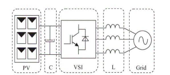
| Fig. 1 shows the basic structure of a single-stage three-phase grid-connected PV system studied in
this paper. This
system consists of a PV array, an input filter capacitor C, a three-phase VSI, an output filter inductor
L, and grid. The
PV modules are connected in a series–parallel configuration to match the required dc voltage and
power rating. The
input capacitor supports the solar array voltage for the VSI. The three-phase pulse width-modulated
inverter with a
filter inductor converts a dc input voltage into an ac sinusoidal voltage by means of appropriate switch
signals to make
the output current in phase with the utility voltage and obtain a unity power factor. |
A. Solar Cell and PV Array Model |
| A PV generator is a combination of solar cells, connections, protective parts, supports, etc. In the
present modeling, the
focus is only on cells. Solar cells consist of a p-n junction; various modeling’s of solar cells
have been proposed in the
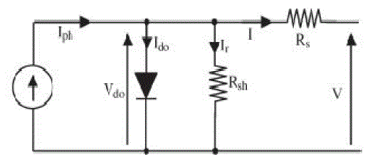
literature. Thus, the simplest equivalent circuit of a solar cell is a current source in parallel with a
diode. The output of
the current source is directly proportional to the light falling on the cell (photocurrent). During
darkness, the solar cell
is not an active device; it works as a diode, i.e., a p-n junction. It produces neither a current nor a
voltage. Thus, the
diode determines the I–V characteristics of the cell. For this paper, the electrical equivalent
circuit of a solar cell is
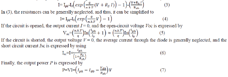
shown in Fig. 2 The output current I and the output voltage of a solar cell are given by |
 |
| Here, Iph is the photocurrent, I0 is the reverse saturation current, Ido is the average current
through the diode, n is the
diode factor, q is the electron charge (q = 1.6*10-19), k is VSI. |
| the Boltzmann’s constant (k = 1.38*10−23), and T is the solar array panel temperature. Rs
is the intrinsic series
resistance of the solar cell; this value is normally very small. Rsh is the equivalent shunt resistance
of the solar array,
and its value is very large. In general, the output current of a solar cell is expressed by |
 |
VSI MODEL |
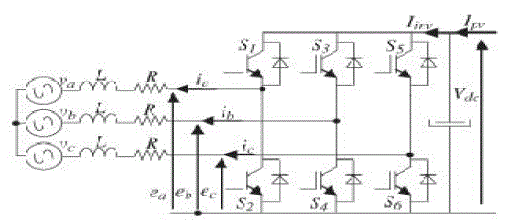
| The VSI connected to the grid through an L filter is shown in Fig. 3. In this section, a dynamic
analytical model of the
VSI is developed in its original three-phase abc frame. Then, this model is transformed into a
synchronous reference
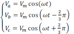
frame. Before analyzing the three-phase VSI, some assumptions are proposed. The three-phase voltages are
sinusoidal
and symmetrical, and their representations are depicted in (8).The switches operate at constant
frequency. The
switching frequency is much higher than the line frequency. The inductors L are linear and balanced.
Saturation is not a
concern. |
| 1) The whole conduction losses are represented by three symmetrical resistors R, as shown in Fig.
3.The absence of
the zero sequence in the currents into a three wire system. |
 (8) (8) |
| Based on the aforementioned assumptions, the model of the VSI in the stationary abc frame is
established as |
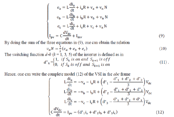 |
| For pulse width modulation (PWM) inputs, the aforementioned model can be separated into low- and
high-frequency
components using the Fourier analysis. The high-frequency model is concerned with the switching behavior
of the
inverter and is almost neglected. The low-frequency model, which has the same expression as (12), with
the switching
functions d* being replaced by continuous duty ratios dk(k = 1, 3, 5) ∈ [0, 1], is much more
considered |
 |
| It is noted that the model (12) is time varying and nonlinear. In order to facilitate the control, the
model can be
transformed into a synchronous orthogonal frame rotating at the angular frequency of the utility
ω. With this timevarying
transformation, given by (13), the positive sequence components at the fundamental frequency become
constant.Finally, the whole dynamic model (14) in the dq frame is obtained from (12) and (13) |
 |
| id, iq d- and q-axis grid currents, respectively; νd, νq d- and q-axis grid voltages,
respectively; dd, dq d- and qaxis
duty ratios. |
3.1 Current And Voltage Controllers |
| According to [19], VOC strategy guarantees fast transient response and high static performance via
internal current
control loops. |
A. Current Control |
| It can be seen from (14) that there is cross-coupling between the d and q components. However, cross-
coupling can
affect the dynamic performance of the regulator. Therefore, it is very important to decouple the two
axes for better
performance. This effect can be accomplished with the feed forward decoupling control method. Assuming
that |
| vrd = -vd+ddvdc+ωLiq |
 |
| The cross-coupling variables are eliminated in the aforementioned model. Hence, the currents id and iq
can be
controlled independently by acting upon inputs Vd and Vq, respectively. Furthermore, by using PI-type
regulators, a
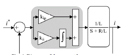
fast dynamic response and zero steady-state errors can be achieved. The diagram of the current regulator
is shown in
Fig. 4. Since the switching frequency is much higher than the line frequency, the sampling and hold
delay is neglected.
the diagram, kip and kii are the proportional and integral parameters, respectively; i* is the reference
current signal, and
I is the feedback current. The diagram is suitable for both id and |
| iq loops. From the diagram, the closed-loop transfer function of the d, q current loops is |
 |
B. Voltage Control |
| In the case of a unity power factor (iq= 0) and with the previous assumption, the third
equation in the model (14) is
repeated as |
 |
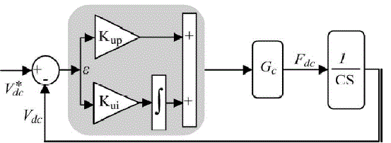
| The closed-loop transfer function of dc voltage regulation, obtained from Fig. 5, has the following
form: |
 |
3.2 MPPT |
| The dc voltage controller is used to produce the reference current value for the id current
controller. Its aim is to keep
the voltage constant on the dc side in normal condition or during rapidly changing atmospheric
conditions. The MPPT
algorithm modulates the reference voltage V ∗ dc according to the environmental conditions in
order to keep the
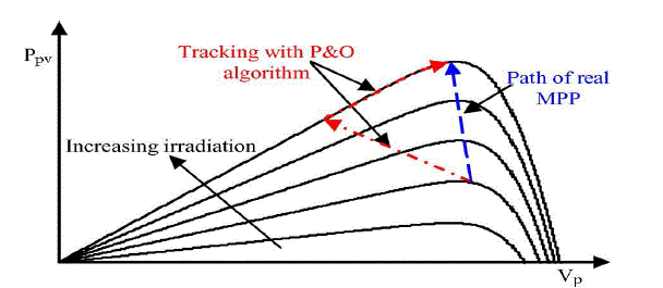
operating point of the PV panels close to the MPP. In the conventional P&O method, the MPP is
obtained from the PV
array power by multiplying the voltage and current of PV arrays and comparing it with the previously
measured power.
In the case of a sudden increase in irradiance, the P&O algorithm reacts as if the increase occurred
as a result of the
previous perturbation of the array operating voltage. The next perturbation, therefore, will be in the
same direction as
the previous one. Assuming that the system has been initially oscillating around the MPPT, the path of
this behavior is
drawn in Fig. 6. It can be seen that a continuous perturbation in one direction will lead to an
operating point far away
from the actual MPP. This process continues until the increase in irradiance slows down or ends. |
| The MPPT controller is applied to the reference of the outer loop control dc voltage photovoltaic
(PV).Without PV
array power measurement, the proposed MPPT identifies the correct direction of the MPP by processing the
d-axis
current reflecting the power grid side and the signal error of the FUZZY outer loop designed to only
represent the
change in power due to the changing atmospheric conditions. The robust tracking capability under rapidly
increasing
and decreasing irradiance is verified experimentally with a PV array emulator. To overcome the
limitations of the P&O
method, the proposed MPPT enables us to decouple the change in power caused by the simultaneous
increment
perturbation and irradiation variation. The irradiation variation is estimated by using the signal error
of the PI controller
of the dc voltage control. The PI regulator is designed to assure zero signal error if the atmospheric
conditions are
constant and a constant signal error in the opposite case. Hence, the signal error reflects only the
change in power
caused by the irradiation variation. After that, in order to calculate the total change in the PV array
power, the d-axis
grid current component is used. Finally, the change in power caused by the previous perturbation is
obtained by a
simple subtraction; therefore, the correct direction of the MPP can be identified. |
A. PV Power Calculation |
| In the synchronous rotating frame d, q, the active and reactive powers of a three-phase grid-connected
VSI are given by |
 |
 |
| Assuming lossless power transmission between solar array and grid line, the relationship of
instantaneous active power
exchanged between the PV array and the grid is given by |
 |
B. Signal Error of Outer Voltage Regulator |
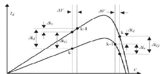
| The change of d-axis current in one period sampling Te under irradiation variation is expressed by the
following: |
 (28) (28) |
| Δiv(k) is the change of d-axis current component caused by the tracker perturbation,
and Δi (k) is the change of d-axis
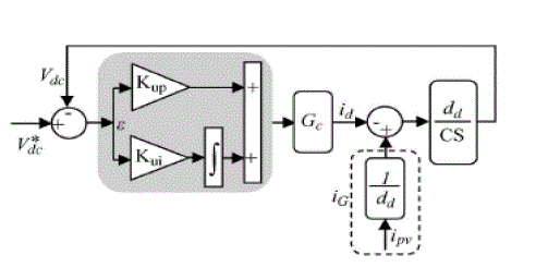
current component caused by the change in irradiation Fig. 7. Thus, the dc bus-voltage control loop
under changing
irradiation can be modeled with the block diagram of Fig. 8, where the current of PV array is an input
disturbance. In
this case, the error |
| between voltage reference V*dc
and voltage measurement Vdc is the following: |
 |
 |
| To calculate the signal error, we use the final value theorem for Laplace transforms. According to
this theorem, as long
as ε(s) |
| does not have any poles in the right half of the complex plane, except maybe s = 0, then |
 |
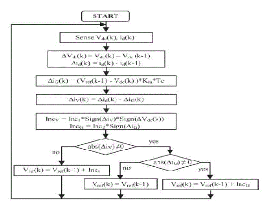
| The flowchart of the proposed MPPT is shown in Fig. 9. The first step is to set up a fixed voltage
whose value is about
0.8 times of the PV array open-circuit voltage. Then, the instantaneous voltage of the PV array and the
d-axis grid
current component are measured using the saved previous voltage and current in order to calculate the
differential
values of Δid and ΔVdc. After that, the ΔiG and ΔiV are calculated by using (35)
and (28), respectively. With this
information, two increments are calculated. The first IncV will be used when the PV array voltage is far
away from the
MPP voltage and the second IncG when irradiance change is present and the PV array voltage is initially
equal to the
voltage of the MPP. In the next test, if abs(ΔiV ) is more than zero (the power change caused by
the previous tracker
perturbation is different from zero), the reference voltage of the PV array is given by adding IncV to
the previous
reference voltage (IncV can be positive or |
MODELLING OF CASE STUDY AND SIMULATION RESULTS |
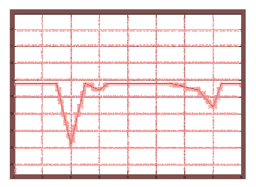
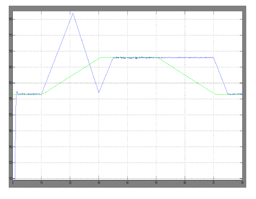
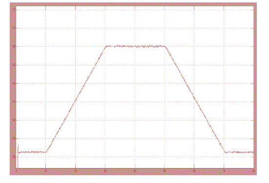
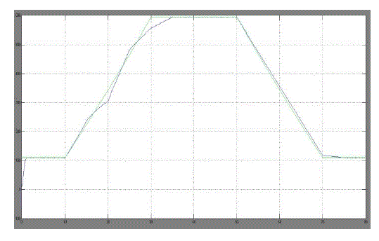
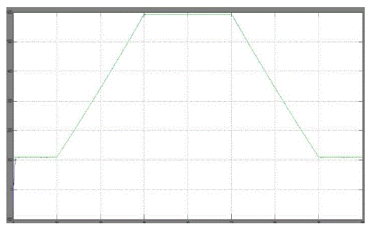
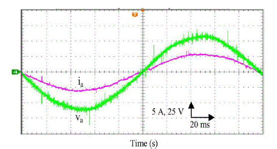
| From the above simulated results we can identify the instantaneous efficiency with modified MPPT using
FUZZY
Controller , PV system voltage with the modified MPPT and theoretical MPP voltage during a trapezoidal
irradiation
profile and PV array power during a trapezoidal irradiation profile using the classical P&O MPPT
method, compared
to the theoretical MPP power are improved. |
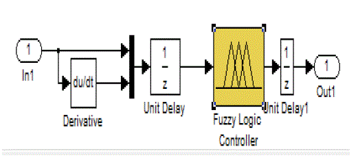
| Fuzzy logic control circuit is implemented in MAT LAB is shown in below fig. |
| This section presents the simulation results of the classical P&O and the proposed method in order
to validate the
performance of the control scheme. Computer simulation has been done using MATLAB/SIMULINK simulation
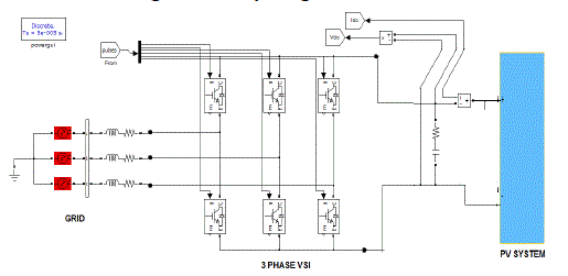
package. The full diagram of the control methodology and the modulation is shown in Fig. 10. The
characteristics of
Solar PV module are used for the PV array model in the simulation and experiment. The 60 module provides
60 W of
nominal maximum power and a 21.1-V open-circuit voltage at an irradiation of 1 kW/m2 and an ambient
temperature
of 25 ◦C. To compare the performance of the proposed MPPT method with that of the P&O method,
the simulations are
configured under exactly the same conditions to compare the performances. The PV array in simulation is
composed of
ten series connected modules. The sampling period used for MPPT algorithm is chosen as 0.2 s, and
voltage increments
of Inc1 = 0.5 V and Inc2 = 0.1 V are used.In order to verify the effect of rapidly changing irradiation,
an irradiation
ramp change was used. A 20-s period for the increasing and decreasing ramps was selected. This
irradiation change
starts from 200 W/m2, stops at 1000 W/m2, waits at this level for 20 s, and decreases again back to 200
W/m2 with a
constant slope. The temperature is considered constant during the simulation. |
CONCLUSION |
| In order to avoid possible mistakes of the classical MPPT algorithm with PI control due to the fast-
changing irradiation,
this paper a FUZZY based MPPT-SRF Configuration of a Single Stag Grid-Connected PV System Inverter Based
On
Voltage-Oriented Control has proposed an improved MPPT controller. Our control scheme uses the d-axis
grid current
component and the signal error of the FUZZY outer voltage regulator. This MPPT method permits one to
differentiate
the contribution of increment perturbation and irradiation change in power variation, hence identifying
the correct
direction of the MPP. In the simulation and experimental results, the robust tracking capability under
rapidly increasing
and decreasing irradiance has been proved. Moreover, the output power losses caused by the dynamic
tracking errors
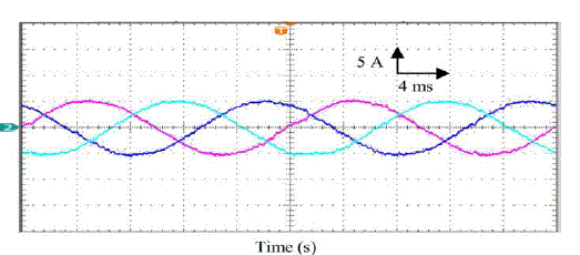
are drastically reduced, particularly under fast changing irradiation. With proposed fuzzy controller we
achieved
improved wave shapes in ac voltages and also maintain unity power factor. |
Figures at a glance |
 |
 |
 |
 |
 |
| Figure 1 |
Figure 2 |
Figure 3 |
Figure 4 |
Figure 5 |
 |
 |
 |
 |
 |
| Figure 6 |
Figure 7 |
Figure 8 |
Figure 9 |
Figure 10 |
 |
 |
 |
 |
 |
| Figure 11 |
Figure 12 |
Figure 13 |
Figure 14 |
Figure 15 |
 |
 |
 |
 |
 |
| Figure 16 |
Figure 17 |
Figure 18 |
Figure 19 |
Figure 20 |
 |
| Figure 21 |
|
References |
- RiadKadri, Jean-Paul Gaubert,
Member, IEEE, and Gerard Champenois, Member, IEEE “An Improved Maximum Power Point
Tracking forPhotovoltaic Grid-Connected Inverter Based on Voltage-Oriented Control” IEEE TRANSACTIONS
ON INDUSTRIAL ELECTRONICS, VOL. 58,NO. 1, JANUARY 2011
- C. Meza, J. J. Negroni, D. Biel, and F.
Guinjoan, “Energy-balance modeling and discrete control for single-phase grid-connected PV
centralinverters,” IEEE Trans. Ind. Electron., vol. 55, no. 7, pp. 2734–2743, Jul.
2008.
- B. Sahan, A. N. Vergara, N. Henze, A.
Engler, and P. Zacharias, “A singlestage PV module integrated converter based on a low-
powercurrentsource inverter,” IEEE Trans. Ind. Electron., vol. 55, no. 7, pp. 2602–2609,
Jul. 2008.
- K. Hemmes, “Towards multi-source
multi-product and other integrated energy systems,” Int. J. Integr. Energy Syst., vol. 1, no.
1, pp. 1–15, Jan.–Jun. 2009.
- F. Liu, Y. Zhou, S. Duan, J. Yin, B.
Liu, and F. Liu, “Parameter design of a two-current-loop controller used in a grid-connected inverter
systemwith LCL filter,” IEEE Trans. Ind. Electron., vol. 56, no. 11, pp.
4483–4491, Nov. 2009.
- T. Shimizu, O. Hashimoto, and G.
Kimura, “A novel high-performance utility-interactive photovoltaic inverter system,” IEEE
Trans. PowerElectron., vol. 18, no. 2, pp. 704–711, Mar. 2003.
- T. Esram, J. W. Kimball, P. T. Krein,
P. L. Chapman, and P. Midya, “Dynamic maximum power point tracking of photovoltaic arrays using
ripplecorrelation control,” IEEE Trans. Power Electron., vol. 21, no. 5, pp. 1282–1291,
Sep. 2006.
- N. Femia, G. Petrone, G. Spagnuolo,
andM. Vitelli, “Optimization of perturb and observe maximum power point tracking method,”
IEEE Trans.Power Electron., vol. 20, no. 4, pp. 963–973, Jul. 2005.
- G. Carannante, C. Fraddanno, M. Pagano,
and L. Piegari, “Experimental performance of MPPT algorithm for photovoltaic sources subject
toinhomogeneous insolation,” IEEE Trans. Ind. Electron., vol. 56, no. 11, pp. 4374–4380,
Nov. 2009.
- N. Femia, G. Petrone, G. Spagnuolo,
and M. Vitelli, “Perturb and observe MPPT technique robustness improved,” in Proc. IEEE Int.
Symp. Ind.Electron., 2004, vol. 2, pp. 845–850.
- K. H. Hussein, I. Muta, T. Hoshino,
and M. Osakada, “Maximum photovoltaic power tracking: An algorithm for rapidly changing
atmosphericconditions,” Proc. Inst. Elect. Eng.—Gener.,Transm. Distrib., vol. 142, no.
1, pp. 59–64, Jan. 1995.
- N. Femia, G. Petrone, G. Spagnuolo,
and M. Vitelli, “A technique for improving P&O MPPT performances of double-stage grid-
connectedphotovoltaic systems,” IEEE Trans. Ind. Electron., vol. 56, no. 11, pp. 4473–
4482, Nov. 2009.
|