Keywords
|
| Parallel coupled microstrip filter, Band Pass filter, Transmission line theory approach, MATLAB simulator |
INTRODUCTION
|
| The development of the frequency bands in microwave engineering filters, play an important role in many RF circuits and microwave applications [1]. Obviously, filters are an essential part of telecommunications and radar systems, consequently are the key items in the performance and cost of such systems. Of its low-cost fabrication, easy integration and simple designing procedure, the parallel coupled-line/edge-coupled filters are widely used in microwave microstrip circuits with a required bandwidth up to 20 % of central frequency [2] [3]. To calculate the critical coupled line parameters of this type of filters, generally authors use the EM Commercial simulators. Nevertheless, these simulators cannot allow the whole parameter calculations necessary to build the filters design. By the way, they are obligated to realize many numerical operations to obtain the rest of the desired parameters, particularly for each case of filter under study. The principal objective of this work is to propose a novel MATLAB interface based on the transmission line theory approach, to allow the scientist and engineers demand to obtain the whole parameters required to approximate the PCMBPF design parameters, providing a high precision and accuracy of numerical results with a small CPU time calculations. As can be detailed in this work, all calculation parameter steps are numerically programmed and efficient results are obtained. Therefore, the overall transmission matrix is determinate and the results are depicted in the same proposed MATLAB interface for each design under study. Note that, the interface presented in this paper can be also generated to other case of planar parallel coupled filter designs for any desired technology. |
THEORY OF PARALLEL COUPLED MICROSTRIP BAND PASS FILTERS
|
| A. MICROSTRIP TRANSMISSION LINE |
| Microstrip transmission line is the most used planar transmission line in radio frequency (RF) applications [4]. The planar configuration can be achieved by several ways, for example with the photolithography process or thin-film and thick film technology. As other transmission line in RF applications, microstrip can also be exploited for designing certain components, like filters, couplers, transformers or power dividers. As can be shown in Figure 1, the microstrip transmission line is widely used to transport the information with a relative low frequency; the fundamental mode propagating through this kind of transmission line is called a quasi-TEM wave. The width of the strip W together with the dielectric constant εr and the thickness of the substrate in one hand determine the characteristic impedance Z0 and on the other hand the rest of the whole parameters required to design the filter [4]. |
| B. PARALLEL COUPLED MICROSTRIP FILTER |
| Figure 2 illustrates a general structure of parallel-coupled microstrip band-pass filters that use half-wavelength line resonators [5]. These lines are positioned so that adjacent resonators are parallel to each other along half of their length. This parallel arrangement gives relatively large coupling for a given spacing between resonators. Furthermore, and in comparison with the structures for the end-coupled microstrip filters, the lines distribution structure demonstrated in Figure 2 is particularly convenient for constructing filters having a large bandwidth. |
| The coupling gaps correspond to the admittance inverters in the low-pass prototype circuit Even and Odd mode characteristic impedances of parallel-coupled half-wave resonators are computed using admittance inverters. These even and odd mode impedances are then used to compute physical dimension of the filter [6]. In this way, the required parallel coupled microstrip filter parameters can be easily derived for Chebyshev prototypes [7] [10]. |
| C. N-POLE CHEBYSHEV COUPLED LINE FILTER |
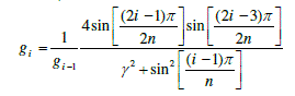
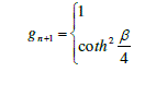
| The first step in designing a parallel coupled band pass filter is to determine the element values for Chebyshev response based on the design specification; an order filter is required for any wireless communication technology. The element values for nth order using the ripple low pass filter are determined from equations (1) to (3), [2] [8]. |
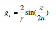 (1) (1) |
 (2) (2) |
| For i=2 to n (n is the order of the filter) |
 (3) (3) |
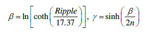
| Where: |
 |
| The strips are arranged parallel close to each other, so that they are coupled with certain coupling factors. We use the following equations for designing the parallel-coupled filter [5] [9]. |
 (4) (4) |
| For j=1 to n-1: |
 (5) (5) |
 (6) (6) |
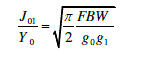
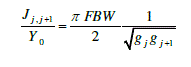
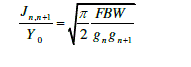
| Where g0, g1… gn are the element of a ladder-type low-pass prototype with a normalized cut-off Ωc = 1, and FBW is the fractional bandwidth of band-pass filter. J j, j+1 are the characteristic admittances of J-inverters and Y0 is the characteristic admittance of the terminating lines. The equation above will be used in end-coupled line filter because the both types of filter can have the same low-pass network representation. However, the implementation will be different. |
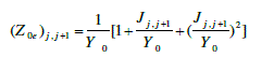
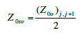
| To realize the J-inverters obtained above, the even- and odd-mode characteristic impedances of the coupled microstrip line resonators are determined by [8] [10]. |
| Then we have: |
| For j=0 to n |
 (7) (7) |
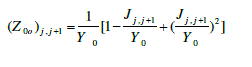 (8) (8) |
| The next step of the filter design is to find the dimensions of coupled microstrip lines that exhibit the desired evenmode and odd-mode impedances. Firstly, we determine the equivalent single microstrip shape ratios (w/h)s, essentially responsible to relate the coupled line ratios to single line ratios. For a single microstrip line, |
 (9) (9) |
 (10) (10) |
| For a single microstrip line, The approximate expressions for W/h (Figure 1) in terms of Zc and εr, derived by Wheeler [11] and Hammerstad [3], are available. |
| For W/h ≤ 2 |
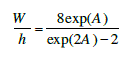 (11) (11) |
| with |
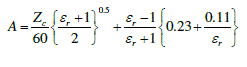 |
| For W/h ≥ 2 |
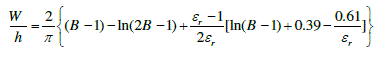 (12) (12) |
| with |
 |
| At that point, it’s able to find (W/h)se and (W/h)so by applying Z0se and Z0so (as Zc) to the single line microstrip equations. Now it comes to a point where it reach the w/h and s/h for the desired coupled microstrip line using a family of approximate equations as following [10,12]: |
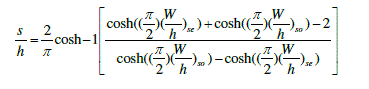 (13) (13) |
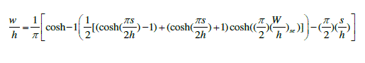 (14) (14) |
| Once the width and spacing have been calculated for each pair of quarter-wavelength coupled sections, the guided wavelength of the quasi-TEM mode of microstrip can be given by: |
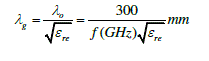 (15) (15) |
| Thus the required resonator, |
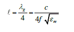 (16) (16) |
| The effective dielectric constant εre of a microstrip is given by [8]. The closed-form expressions that provide accuracy better than one percent are given in [13] as follows: |
| For wide line microstrips, W/h ≥ 1 |
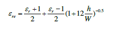 (17) (17) |
| For narrow line microstrips, W/h ≤ 1 |
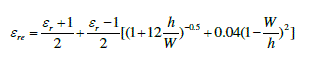 (18) (18) |
MATLAB INTERFACE CALCULATOR
|
| As mentioned earlier, one of our principal objectives in this paper is the creation of a new MATLAB interface to estimate the parameters of the band pass filters under study with a very high precision, avoiding the errors of calculation that can commit the engineers and the scientists throughout the design of this type of filters. as can be shown, to create the new and efficient calculator interface, all formulas of a parallel coupled band pass filter developed previously based on the transmission line theory approach, are implemented, in the new MATLAB interface to calculate the parameters required to design the response of this type of filter. |
| A. EQUIVALENT CIRCUIT OF THE PARALLEL COUPLED BAND PASS FILTER |
| The equivalent circuit for derivation of design equations for a parallel coupled line band pass filter is show in Figure 3. In the transformation to a band pass characteristics, the component L will be converted to serial combinations of Ls and Cs, whereas the component C becomes parallel combination of Lp and Cp with the cut-off frequencies ω1 and ω2 as lower and upper boundary. |
| The center frequency and the relative frequency bandwidth can be calculated as follows: |
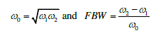 |
| The parameter values for the new components for the serial and the parallel combination respectively are: |
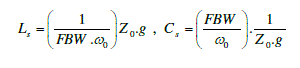 (19) (19) |
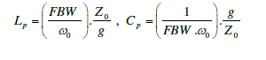 (20) (20) |
| Z0 is the value of the load impedance, normally set to 50 Ω. |
| To obtain the S-parameters of this type of filters, as a first step we convert the Z-matrix obtained for each coupled section to the equivalent ABCD, these ABCD matrices were multiplied to obtain the overall transmission matrix. Finally the required matrix manipulations are done and the results are plotted in the MATLAB interface. |
| B. RESULT AND DISCUSSIONS |
| For a good way of understanding the theory of type of filters studied previously, Figure 4 and Figure 5 shows the new MATLAB interface developed in this paper. To proceed to use the new calculator interface, first we do doubleclick into the bottom A Parallel Coupled Microstrip Band-Pass Filter calculator parameters, Figure 4. Immediately a new interface will appear, is the one in Figure 5. Before proceeding to resolve the filter parameters under study, we note that the new interface has been developed to estimate the band pass filter parameters in the general case, precisely for the filters of order n. As shown in the Figure 5, to represent the parameters S it is necessary first to specify the initial values of the filter in their fields in the interface. As an example, we chose to study a filter of order 3, then we input the order of the filter and the equal band pass ripple to calculate the Chebyshev elements values of equations 1, 2 and 3, secondly we input the center frequency and the bandwidth associated to calculate the normalized transformer admittances and even and odd-mode characteristic impedances of the coupled microstrip line resonators mentioned previously in equations 4, 5, 6, 7 and 8. |
| Based on these characteristic impedances and using the transmission line theory approach of equations 13 and 14, we can calculate the physical dimensions of this filter; the width, the length and the space gap between microstrip line sections. A button case test is used to test the W/h corresponding case of equations 11, 12, 17 and 18 to calculate the w/h and the s/h for all section and the effective dielectric necessary to calculate the length of these sections. |
| Using this MATLAB interface calculator, the results obtained for a parallel coupled microstrip band pass filter for the ISM band with the design specifications of Table I are presented in Figure 6. |
| This interface can be used for any order to obtain all parameters necessary to the edge band pass filter design for particular wireless systems applications, with the same characteristics as in Figure 1. The required parameters to design filters are calculated without errors and with a maximum accuracy for any wireless communication technologies. |
| By the same way, we present another example of a parallel coupled microstrip band pass filter with an order of 5 for FM wireless applications using the design specifications of Table II. The results obtained for this filter by the calculator developed in this work are shown in Figure 7. |
CONCLUSION
|
| In this paper, one of our goals has been to present the procedure to design an N-poles Chebyshev parallel coupled microstrip band pass filters for any technology band. The second goal has been to develop a new MATLAB interface using the mathematical analysis and the coupling matrix concept, based on the transmission Line theory approach. The main objective of this interface, is to facilitate the work of engineers and scientists in calculating with a high accuracy and small CPU time, any parameters to design a parallel coupled microstrip band pass filters w. The results obtained with the use of this MATLAB interface have been shown to be in very good agreement with the commercial electromagnetic simulators. In future, our research will focus on extending this interface to design other king of filters, such as parallel coupled microstrip low-pass, high-pass and cut-off filters. |
| |
Tables at a glance
|
 |
|
| Table 1 |
Table 2 |
|
| |
Figures at a glance
|
 |
 |
 |
 |
| Figure 1 |
Figure 2 |
Figure 3 |
Figure 4 |
|
|
|
| Figure 1 |
Figure 2 |
Figure 3 |
|
| |
References
|
- J. S. Hong, M. J. Lancaster, “Microstrip Filter for RF/Microwave Applications”, A Wiley Interscience Publication, Canada, 2001.
- G. Matthaei, L. Young, and E. M. T. Jones, “Microwave Filters, Impedance-Matching Networks, and Coupling Structures”. Boston, MA: ArtechHouse 1980, pp.583-650.
- Hong, J. S. and M. J. Lancaster, “Couplings of microstrip square open-loop resonators for cross-coupled planar microwave filters”, IEEE Transactions on Microwave Theory and Techniques, Vol. 44, No. 12, p. 2099-2109, Dec. 1996.
- M. Alaydrus, Transmission Lines in Telecommunication, GrahaIlmu Press, Jogjakarta, 2009 (in Indonesian).
- R. Ludwig, “RF and Microwave Engineering”, University of San Diego. [Online] Available: www.sandiego.edu/~ekim/e194rfs01/filterek.pdf
- Rachid Ahmad Bhatti, Jahangir Khan Kayani, “Design and analysis of parallel coupled microstrip band pass filter”, 2nd International BhurbanConference on Applied Sciences and Technology, Bhurban,Pakisten. June 16-21, pp. 168-176, 2003.
- Miguel Bacaicoa, David Benito, Maria J. Garde, Mario Sorolla and Marco Guglielmi, “New Microstrip Wiggly-Line Filters with Spurious PassbandSuppression”, IEEE Transactions on Microwave Theory and Techniques, vol. 49, no. 9, pp. 1593-1598, September 2001.
- D. M. Pozar, Microwave Engineering, Fourth Edition, Wiley and Sons, 2012.
- Bahareh Rezaei, Mohammad Pooyan and TowhidZargarErshadi, “Using Microstrip Elements in Dual-band Band pass Filter with Parallel Coupled-Lines and Space Mapping Technique”, The Computing Science and Technology International Journal, vol. 2, no. 3, pp. 39-43, September 2012.
- Naghar, O. Aghzout, F. Medina, M. Alaydrus, M. Essaidi, “Study and Design of a Compact Parallel Coupled Microstrip Band-Pass Filter for a 5 GHz Unlicensed Mobile WiMAX Networks,” International Journal of Science and Technology, vol. 2, No. 6, Juin 2013.
- H. Wheeler, “Transmission line properties of parallel strips separated by a dielectric sheet”, IEEE Trans., MTT-13,1965,172-185.
- SinaAkhtarzard, Thomas R. Rowbotham, and Petter B. Johns, “The Design of Coupled Microstrip Lines”, IEEE Transactions on Microwave Theory and Techniques, vol. MTT-23, no. 6, pp. 486-492, June 1975.
- E. O. Hammerstard, “Equations for microstrip circuit design,” in Proceedings of the European Microwave Conference, Hamburg, Germany, 1975, pp. 268–272.
|