Keywords
|
| power quality; dynamic voltage restore; control strategies; minimal energy control |
INTRODUCTION
|
| Voltage sag and swell are two most importance term in power quality (PQ) problems that produced almost 80% of the distribution system PQ problem[1]. According to the IEEE standard, voltage sag is decrease of 0.1 to 0.9 p.u in the rms voltage level at the system frequency and with duration of half cycle to 1 min. voltage sag of down to 70% are much more common then complete outage. Short circuits, starting large motors, sudden changes of load, and energization of transformer are the main cause of voltage sag. Considering the use of sensitive device in modern industries. Different methods of compensation of voltage sags have been used[4]. One of those method is using DVR with energy storage can be used to control power quality problems. A DVR is basically a controlled voltage source installed between the supply and a sensitive load. It injects voltage on the distribution system to compensate any disturbance after load side. The compensation capacity of a particular DVR depends on the maximum voltage injection ability and active power which can be supplied by the DVR[5]. DVR could maintain load voltage unchanged during any kind fault in use of energy storage devices. Battery, super conducting magnetic energy storage system (SEMES) is required to apply active power to DVR at fault time[7]. So this storage energy limitation necessary to minimize energy injection from DVR. In this paper new minimal energy injection technique of restore voltage sage are discussed. |
DVR COMPONENTS
|
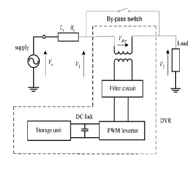
| A typical DVR-connected distribution system is shown in (Fig. 1), where the DVR consists of a voltage-source inverter, series-connected injection transformer, an inverter output filter, and an energy storage device that is connected to the dc link. Voltage source inverter can be controlled three phase injection transformer[8]. Before injecting the inverter output to the voltage, it must be filtered so that harmonics due to switching function in the inverter are eliminated. The injection transformer will be connected in parallel with a bypass switch (Fig. 1). When there is no disturbance in voltage, the injection transformer will be short circuited by this switch to minimize losses and maximize cost effectiveness. Also, this switch can be in the form of two parallel thyristors, as they have high on and off speed. A financial assessment of Voltage sag events and use of flexible ac transmission systems (FACTS) devices, such as DVR, to mitigate them is provided. It is obvious that the flexibility of the DVR output depends on the switching accuracy of the pulse width modulation (PWM) scheme and the control method. The PWM generates sinusoidal signals by comparing a sinusoidal wave with a saw tooth wave and sending appropriate signals to the Inverter switches. |
DVR OPERATIONAL PRINCIPLE
|
| The DVR system shown in Fig. (1) Controls the load voltage by injecting an appropriate voltage phasor (VDVR) in series with the system using the injection series transformer [9]. In most of the sag compensation techniques, it is necessary that during compensation, the DVR injects some active power to the system. Therefore, the capacity of the storage unit can be a limiting factor in compensation, especially during long-term voltage sags. |
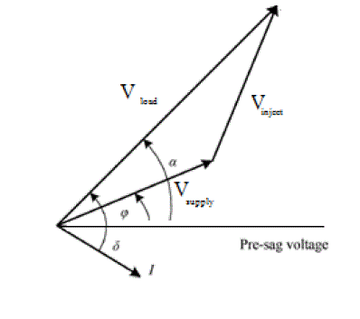
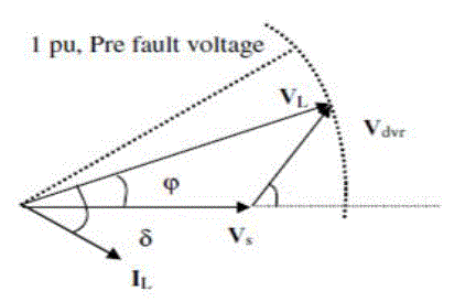
| The phasor diagram in Fig.( 2) shows the electrical conditions during voltage sag, where, for clarity only one phase is shown. the operators I, δ , π are the load current, the load power factor angle, and the voltage phase advance angle, respectively (13) . It should be noted that in addition to the in-phase injection technique. One of the advantages of this method over the in-phase method is that less active power should be transferred from the storage unit to the distribution system. This results in compensation for deeper sags or sags with longer durations. Due to the existence of semiconductor switches in the DVR inverter, this piece of equipment is nonlinear. However, the state equations can be liberalized using linearization techniques. The dynamic characteristic of the DVR is influenced by the filter and the load. Although the modeling of the filter (that usually is a simple LC circuit) is easy to do, the load modeling is not as simple because the load can vary from a linear time invariant one to a nonlinear time-variant one. In this paper, the simulations are performed with two types of loads: 1) a constant power load and 2) a motor load. |
CONVENTIONAL CONTROL STRATEGIES
|
| There are many conventional methods available for voltage sag compensation and the control methods are chosen based on the following factors, type of the loads and energy storage. The types of the load are sensitive load and phase angle jump. The conventional methods are (i) pre-sag compensation (ii) in phase compensation (iii) minimum energy injection control. |
| A. PRE-SAG COMPENSATION METHOD |
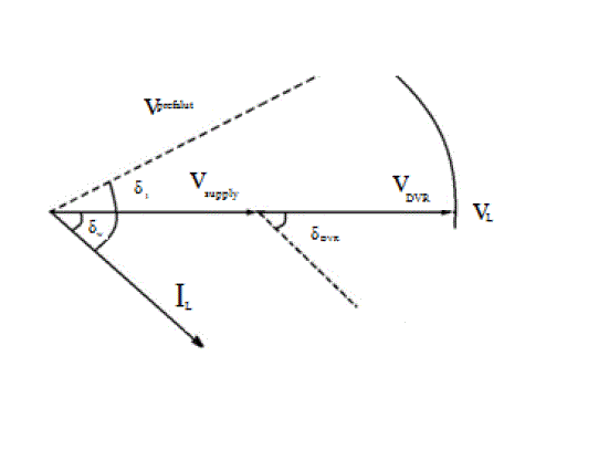
| In this fig (3), compensation takes the DVR injected voltage is different between load voltage and supply voltage in fault condition. In pre-sag condition, DVR injected to compensated voltage magnitude and phase angle but in this method main drawback is it’s not controlled active power. |
 |
| B. IN-PHASE COMPENSATION METHOD |
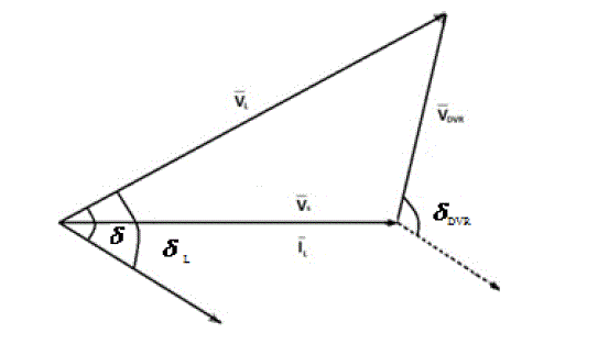
| In this method DVR injected voltage magnitude is compensation. DVR injected voltage is in phase to the fault supply voltage so that reason minimized the injected voltage from DVR and reduced the DC store capacity. In this method should DVR injected only pre sag voltage .mostly used in phase compensation is un sensitive loads but this method main drawback is its intentioned more active power |
 |
| C. MINIMAL ENERGY TECHNIQUE |
| Above two conventional methods are DVR injected voltage Vdvr have more active power so redused that power due to limited DC storage capacity . in this below diagram for minimal energy technique, load current perpendicular to the injected voltage .now vdvr injected active power is zero , more reactive power will be injected . in this paper improve to the reduced active power. |
 |
| if supply voltage satisfy the bellow condition than the value of δ is feasible |
 (7) (7) |
| In above equations (7) is determine the sag level is shallow sag or deep sag. Deep sag means in above equations is equal .if the above equations is in equals means the sag is shallow sag. in shallow sag means DVR injected voltage is equal to the zero if deep sag means DVR injected voltage not equal to the zero. It should injected voltage. |
| D. SUGGESTED CONTROL STRATEGY |
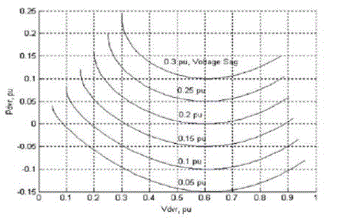
| In this previous section injection active power PDVR is zero at shallow sag. when deep sag is occurs the PDVR is not equal to the zero in figure (6) supply voltage Vs and the load current increases it affected the active power and β values. it result to become increases to the above two values. The relationship between the active power and DVR injected voltage. Show in the figure(6) with power factor 0.8 p.u. |
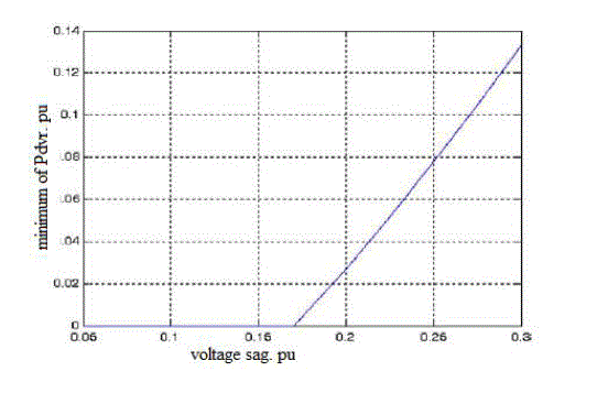
| Pdvr injected power value is zero between sag value is 0 to 2 p.u .in this case Pdvr is negative side so more active power not required because no economical advantages. In consensual method the reactive power is small active power is high but minimum injection method active power injected small level and reactive power will be high. In this paper will be improved the minimum energy injection . bellow diagram the relationship between injection active power Pdvr and inject active power in balanced 3̉̉ voltage sag. |
| Negative PDVR value of minimum injection active power is zero because not give economical advantages of due to limited storage capacity. The positive Pdvr value side of minimum active power will be injected .this power value estimated given bellow equation. |
 |
| The voltage sags mentioned earlier were balance three-phase. For unbalance voltage sages, the three-phase instantaneous values of Vs, i.e., (Vsa, Vsb, Vsc) generate negative and positive sequence voltages. |
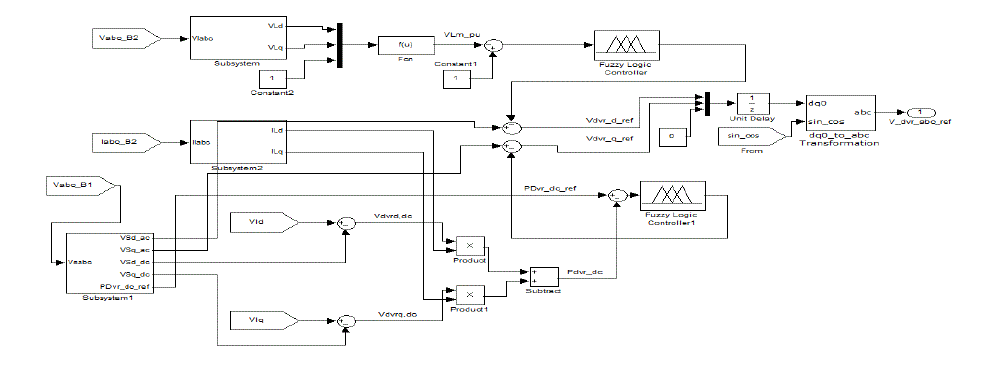
| The output Vdvr,ref and Vdrq value we get in conversion use park transformation from the 3phase load (abc) voltage frame to the dq reference. |
| The output Vdvr,ref and Vdrq value we get in conversion use park transformation from the 3phase load (abc) voltage frame to the dq reference |
| VLd,VLq output apply to the bellow math function |
 |
| Output we will get VLm,pu .this value compare to the VLm,ref,pu using comparator . the error signal applied to the fuzzy logic controller |
| In this project the compensation of load voltage for unbalance voltage sags, DVR Injects DC component of active power, Pdvr, dc that restores fundamental components Of voltage sags and in the same time injects AC component of active power, Pdvr, ac that restores negative sequence components of voltage sags active power Pdvr, dc can be calculated as follows: |
 |
| The, Pdvr, dc, ref and the feedback difference between reference values value, Pdvr, dc passes through the fuzzy controller and the output of the fuzzy controller is added to the q axis AC component of Vs. |
SIMULATION RESULTS
|
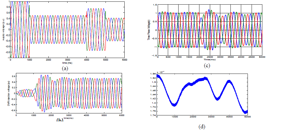
| System shown in fig (8) has been modeled by PSCAD/EMTDC to study the efficiency of suggested control strategy. The system parameters are listed in table 1. It is assumed that the voltage magnitude of the load bus is maintained at 1 pu during the voltage sag conditions. The results of the most important simulations are represented in Figs. 8. |
| The three-phase instantaneous values of DVR left hand side voltage, Vs, i.e., (Vsa,Vsb, Vsc), injected voltage, Vdvr ,load voltage, VL (or VLa, Lb,VLc) and DC component of injected active power, Pdvr, dc have been shown in Fig.8(a), (b), (c) and (d) for a case with a 0.146 pu balance three-phase voltage sag which has happened at t = 0.7 s. In this case DVR works in the suggested control strategy mode. |
CONCLUSION
|
| In order to compensate voltage sag it is possible to use dynamic voltage restorer(DVR) with fuzzy logic control in distribution system for a sensitive load. In this paper the control strategies for the compensation of the supply voltage sag is presented. In addition, a new concept of restoration technique is proposed to inject minimum energy in unbalance sags. Proposed control method makes zero injection power during shallow sag and controls DVR so that injection of power is minimized during deep sag. Simulation results carried out by the PSCAD/EMTDC shows that the proposed method can minimize the injected active power of DVR for a specific apparent power. |
Tables at a glance
|
 |
| Table 1 |
|
Figures at a glance
|
 |
 |
 |
 |
 |
| Figure 1 |
Figure 2 |
Figure 3 |
Figure 4 |
Figure 5 |
 |
 |
 |
 |
| Figure 6 |
Figure 7 |
Figure 8 |
Figure 9 |
|
References
|
- A.Choi., B.H. Li, D.M. Vilathgamuwa, (2010) Design and analysis of the inverter-side filter used in the dynamic voltage restorer, IEEE Transactions on Power Delivery Journal 17 (3).
- A.Ramasamy, V.K. Ramachandaramurthy, R.K. Iyer, Z.L. Liu,( 2007). “Control of dynamic voltage restorer using TMS320F2812”, Electrical Power Quality and Utilization Conference, pp: 1-6.
- A. Ghosh, .and G. Ledwich, (2010). Compensation of Distribution System Voltage Using DVR, IEEE Trans on Power DeliveryJournal, 17(4): 1030-1036. Muni
- C. Zhan, A. Arulampalam, N. Jenkins, (2009) Four-wire dynamic voltage restorer based on a three dimensional voltage space vector PWM algorithm, IEEE Transactions on Power Electronics Conference 18 (4).
- G. Venkataramanan, and M. Illindala, (2006). “Operation and control of a dynamic voltage restorer using transformer coupled H-bridge converters,”IEEE Trans. Power Electron., 21(4): 1053-1061.
|