Keywords
|
| Wind energy, SEPIC converter, Rectifier. |
INTRODUCTION
|
| Since global warming has become a big concern and fossil fuels are eliminating there is a need for another energy source on which we can depend. Wind power generation is an important solution for mitigation the problems due to its smaller environmental impact and its renewable characteristics (5). The conversion of wind energy into a useful form of energy is known as wind power, like wind turbine is used to produce electrical energy. Huge wind farm have large number individual wind turbines which are connected to power transmission network. Around 83 countries in the world are using wind energy for supplying grid and India ranks 5th in the world for the producing electrical energy from wind power(6). |
| Several hybrid wind/PV power systems with MPPT control have been proposed and discussed in works [1]-[5]. Most of the systems in literature use a separate DC/DC boost converter connected in parallel in the rectifier stage as shown in Figure 1 to perform the MPPT control for each of the renewable energy power sources [1]-[4]. A simpler multiinput structure has been suggested by [5] that combine the sources from the DC-end while still achieving MPPT for each renewable source. The structure proposed by [5] is a fusion of the buck and buck-boost converter. The systems in literature require passive input filters to remove the high frequency current harmonics injected into wind turbine generators [6].The harmonic content in the generator current decreases its lifespan and increases the power loss due to heating [6]. |
| In this paper, an alternative multi-input rectifier structure is proposed for hybrid wind/solar energy systems. Theproposed design is a fusion of the Cuk and SEPIC converters. The features of the proposed topology are: 1) the inherent nature of these two converters eliminates the need for separate input filters for PFC [7]-[8]; 2) it can support step up/down operations for each renewable source (can support wide rangesof PV and wind input); 3) MPPT can be realized for each source; 4) individual and simultaneous operation is supported.The circuit operating principles will be discussed in this paper. Simulation results are provided to verify with the feasibility of the proposed system. When a source is unavailable or insufficient in meeting the load demands, the other energy source can compensate for the difference. Several hybrid wind/PV power systems with MPPT control have been Proposedanddiscussed in works [1]- [5]. Most of the systems in literature use a separate DC/DC boost converter connected in parallel in the rectifier stage as shown in Figure 1 to perform the MPPT control for each of the renewable energy power sources [1]-[4]. A simpler multiinput structure has been suggested by [5] that combine the sources from the DC-end while still achieving MPPT for each renewable source. The structure proposed by [5] is a fusion of the buck and buck-boost converter. The systems in literature require passive input filters to remove the high frequency current harmonics injected into wind turbine generators [6].The harmonic content in the generator current decreases its lifespan and increases the power loss due to heating [6].In this paper, an alternative multi-input rectifier structure is proposed for hybrid wind/solar energy systems. The proposed design is a fusion of the Cuk and SEPIC converters. The features of the proposed topology are: 1) the inherent nature of these two converters eliminates the need for separate input filters for PFC [7]-[8]; 2) it can support step up/down operations for each renewable source (can support wide ranges of PV and wind input); 3) MPPT can be realized for each source; 4) individual and simultaneous operation is supported. The circuit operating principles will be discussed in this paper. Simulation results areprovided to verify with the feasibility of the proposed system |
PROPOSED MULTI-INPUT RECTIFIER STAGE
|
| A system diagram of the proposed rectifier stage of hybrid energy system is shown in Figure 2, where one of the inputs is connected to the output of the PV array and the other input connected to the output of a generator. The fusion of the two converters is achieved by reconfiguring the two existing diodes from each converter and the shared utilization of the Cuk output inductor by the SEPIC converter. This configuration allows each converter to operate normally individually in the event that one source is unavailable. Figure 3 illustrates the case when only the wind source is available. In this case, D1 turns off and D2 turns on; the proposed circuit becomes a SEPIC converter and the input to output voltage relationship is given by (1). On the other hand, if only the PV source is available, then D2 turns off and D1 will always be on and the circuit becomes a Cuk converter as shown in Figure 4.The input to output voltage relationship is given by (2). In both cases, both converters have step-up/down capability, which provide more design flexibility in the system if duty ratio control is utilized to perform MPPT control. |
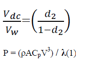 |
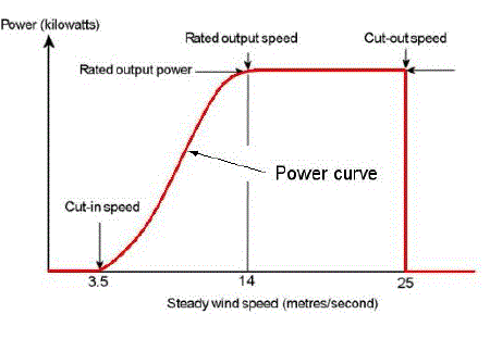
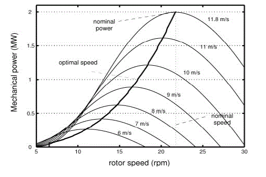
| Where P is the power generated by wind turbine, ρ is the air density; Cp is the Power coefficient which describes the fraction of the wind captured by the wind turbine. Fig. 1 shows a steady wind speed – power curve, which shows the regulated power achievable from the wind turbine. It is seen that at very low speeds the generated power is very less to be utilized. To allow the turbine to transfer a maximum available wind power for fluctuating wind velocities incident upon the turbine blades, it is desirable to maintain the tip – speed ratio at point of maximum power coefficient Cp. Normally in MPPT the production of the reference rotating speed is based on a measurement of the power generated. So the power generated is simpler and more accurate than the measurement of the wind velocity (7). |
SEPIC CONVERTER
|
| Single-ended primary-inductor converter allows electrical potential of output to be greater, less or equal to the input voltage which is controlled by the duty cycle. This converter is similar to buck-boost converter but it has non-inverted output which is an advantage (8). The basic diagram of SEPIC converter is shown in Fig. 2. |
| SEPIC converter exchanges energy between capacitors and inductors in order to convert voltage from one level to another level. The amount of converted voltage level is controlled by MOSFET and the SEPIC converter works in two modes. |
| A. Continuous mode |
| SEPIC converter is in continuous mode when the current through inductor L1 never falls to zero. |
| B. Discontinuous mode |
| SEPIC converter is in discontinuous mode when the current through the inductor L1falls to zero. |
PROPOSED WORK
|
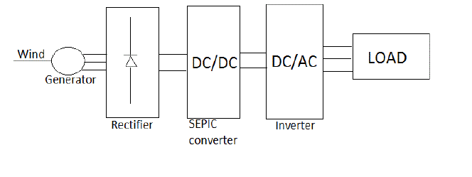
| The block diagram of the proposed work is shown in Fig. 3, the electrical energy generated by the wind is first converted into DC by rectifier. |
| The rectified DC is given to the DC/DC SEPIC converter which converts the input voltage to the desired value, either by stepping it up or stepping it down as required by the load. The use of SEPIC converter eliminates the requirement of filter for the unwanted harmonics in the supply. The output of SEPIC converter is given to the inverter which will convert the DC supply to AC. The output of inverter does not have any unwanted harmonics so it is given to the LOAD. The duty ratio of the converter is controlled by the formula |
| Vdc = (d / 1 – d) Vw (2) |
| Where, Vdc is the generated output voltage of SEPIC converter, ‘d’ is the duty ratio, Vw is the voltage generated by the wind source. |
MPPT CONTROL OF WIND TURBINE
|
| The pitiful drawback of wind system is their intermittent nature of energy source. It is capable of supplying huge amount of power but its presence is highly unpredictable, it can be present in any direction so in order to get maximum efficiency we need to incorporate the MPPT algorithms. The wind power characteristic equation is given by |
| Pm = 0.5ρACp (λ,β)V3 (3) |
| Where,Cp (λ,β) is the power coefficient function and β is the pitch angle. |
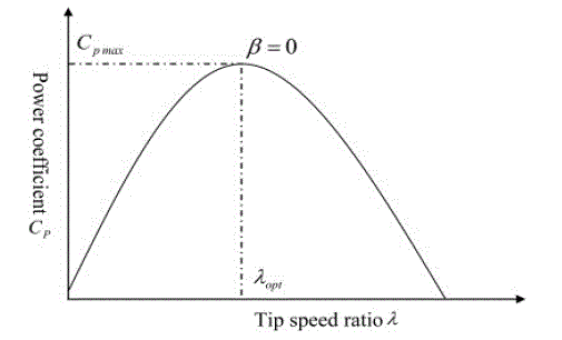
| The power coefficient is dependent on the TSR λ (tip speed ratio) and the pitch angle β. Mathematically TSR is given by |
| λ = RWb / V (4) |
| Where, R is the turbine radius and Wb is the angular rotational speed. Fig 4 and 5 shows the power coefficient curve and power curve for a typical fixed pitch i.e. β = 0 |
RESULT AND DISCUSSION
|
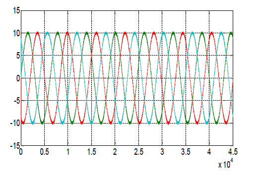
| The proposed work discussed above is simulated using MATLAB software and the following outputs are extracted from the simulation. Fig 6 shows the injected three phase current from the wind source. This current is then given to the SEPIC converter. |
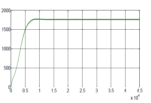
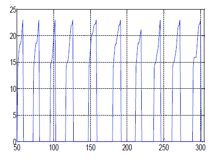
| Fig 7 & 8 shows the output power and switch current (MOSFET) of SEPIC converter. From power curve we can see that maximum power point has been tracked and maximum power has been achieved which is 1.8W. |
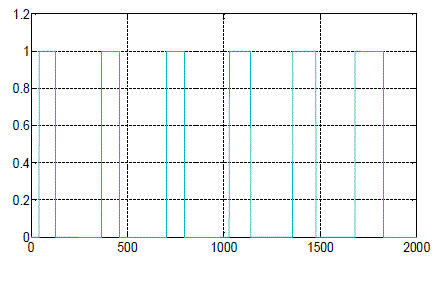
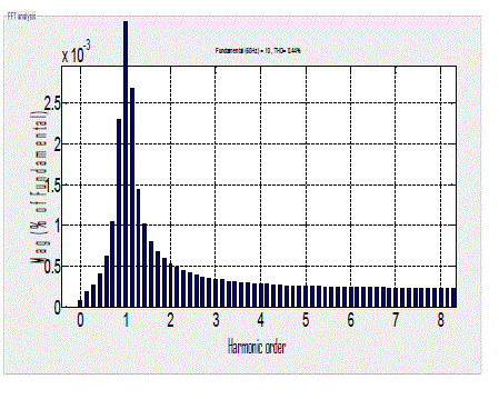
| Fig 9 shows the generated pulse for the inverter in order to get the desired output. Fig 10 shows the FFT analysis of the current and it has been that there no other harmonic component present in the system expect fundamental and THD is 0.44%. |
CONCLUSION
|
| In this paper a new rectifier stage topology with SEPIC converter is presented and it has been seen that after obtaining the MPPT from the wind turbine the SEPIC converter can be used to meet the load demand. The use of SEPIC converter is to reduce the cost of the system since there is no use of high frequency filters because the harmonics content in the system is eliminated the SEPIC converter and it has been seen that the Load demand of 1.8 kW can be achieved without any interruption and the total harmonic content in the system is limited to 0.44%. |
Figures at a glance
|
 |
 |
 |
 |
 |
| Figure 1 |
Figure 2 |
Figure 3 |
Figure 4 |
Figure 5 |
 |
 |
 |
 |
 |
| Figure 6 |
Figure 7 |
Figure 8 |
Figure 9 |
Figure 10 |
|
References
|
- Y.M.Chen, Y.C. Liu, S.C. Hung and C.S.Cheng,”multi-Input inverter for grid-connected Hybrid PV/Wind power system,”IEEE Transactions on Power Electronics, Vol. 22, May 2007.
- Dos reis F.S. tan, K and Islam, S. “using PFC for harmonic mitigation in wind turbine energy conversion systems” in Proc. Of the IECON 2004 Conference, pp.3100-3105, Nov.2004.
- R.W.Erickson, “some Topologies of High Quality Rectifiers”, In the Proc of the first international conference on energy, power and motion control, May 1997.
- D.S.L.Simonetti, J. Sebastian and J.Uceda, “the discontinuous conduction mode SEPIC and cuk power factor preregulators: Analysis and design” IEEE Trans. on Industrial Electronics, Vol.44, no.5, 1997.
- N.Mohan, T.Undeland and W. Robbins, “power Electronics: converters, Application, And Design,” John Wiley & Sons, Inc, 2003.
- F.Lassier and T.G. Ang, “wind turbine handbook” 1992.
- J.Marques, H, pinherio “A survey on Variable Speed Wind turbine system”, proceeding of Brazilian conference of electronics of power vol. 1 pp. 732-738, 2003.
- Global wind energy council (GWEC), “Global wind 2008 report,” June 2009.
- S.K.Kim, J.H.Jeon and S.H.Kwon, “Dynamic modelling and control of Grid-connected hybrid Generation system with Versatile Power Transfer,” IEEE Trans on industrial electronics, vol.55, pp.1677-1688, April 2008.
- S.Jain and V. Agrawl, “An integrated hybrid power supply for Distributed Generation Applications Fed by non-conventional Energy Sources, IEEE Trans. On Energy Conversion, Vol 23, June 2008.
|