Keywords
|
| Cascaded multilevel inverter developed H-bridge, multilevel inverter, level doubling network (LDN), self-balanced multilevel inverter (MLI), power quality. |
INTRODUCTION
|
| Multilevel inverters offer various applications in voltage ranging from medium to high such as in renewable energy sources, industrial, laminators, blowers, fans, and conveyors. Small voltage step results in making the multilevel inverters withstand better voltage, lower harmonics, good electromagnetic compatibility, minimized switching loss, and better power quality[1][2]. Cascaded multilevel inverters were developed in the initial stage. Later, diode- lamped MLI’S were developed followed by lying capacitor MLI’S. These three topologies utilize different mechanisms to produce the required output. the topology introduced first, that is, the CMLI, is simply series connection of Hbridges[ 4][5]. |
| The cascaded multilevel inverter has more advantages than other two topologies [6], [7], since it does not require any balancing capacitors and diodes. Cascaded inverter needs separate DC sources for each H-Bridge, hence there is no voltage balancing problem, but isolated DC sources are not readily available, this could be main drawback of this topology[3]. Cascaded topology requires more switches. |
| Conventional Topology. Using 3 DC voltage sources, 3 H-bridge units each with 4 switches together forming 12 switches in total are used in conventional CMLI which is represented in Figure 1.General expression for output voltage levels, M = (n + 2)/2 where n is the number of switches in the configuration. Each Bridge is outputting 3 Levels, +Vdc, 0, −Vdc. Cascading 3 Bridges in such a fashion to produce stepped 7 level staircase waveforms. |
| Cascaded H-bridge (CHB) MLI is obtained high-quality output voltages and input currents, high reliability due to their intrinsic component redundancy [8] [10]. One of the main technique is induced to increase the number of levels is by asymmetry in voltage ratio of the inverter cells. The asymmetric structure of the MLI is introduced in [4] and [5] and is capable to produce a very high number of levels with a given switch count [2]. For a given topology, the number of levels depends on the configuration of the dc voltage ratio(leading to binary, trinary, and other configurations). in asymmetric structure, powers delivered by the various levels are quite different [8]. While most of the power is delivered by the highest voltage cell [6], the lower voltage cells deal with only a fraction of the same. |
| A floating scheme is presented in binary MLI [7]. This topology proposes, special attention of voltage balancing problem demanding complex control algorithms. This is suitable for high-power applications. Higher voltage and higher number of levels are achieved using low-voltage switch-based power converters and summing transformer. In this topology, high-voltage switches are avoided at the cost of summing transformers. Neutral point clamped (NPC)- CHB hybrid and asymmetric topology are introduced in [9]. A CHB with a dc bus voltage lower than NPC is connected in between the NPC terminal and the load terminals to obtain finer and more numbers of voltage steps. This topology also requires special attention to take care of the voltage balancing problem. This paper proposes a new topology to almost double the number of levels in an MLI, by adding only two switches per phase. |
PROPOSED TOPOLOGY
|
| This does not allow the bridges to be easily replaced (as the high side and low side bridges most likely to be made by different power devices) and hence loses the advantage of modularity. This makes the asymmetric topology not very attractive for medium-voltage (MV) drives and many other applications. Recently, many hybrid multilevel topologies are proposed [10]–[11]. However, the symmetric CHB structure has definite merits in high-power applications due to fault tolerance/reliability and modularity. The recent trend is to use a symmetric MLI fed by a multipulse rectifier [12]– [13] for high- and medium-power applications in industry. Balance its floating capacitor. The capacitors here maintain the voltage by virtue of the self-balancing property of the topology, detailed at a later stage in this work. |
| The single-phase version of the proposed topology is shown in Fig. 1. The topology is realized by adding an extra halfbridge connected to a capacitor that maintains half the voltage of other bridges by a self-balancing mechanism. For a three-phase system, three half-bridges (i.e., one half-bridge per phase) in parallel are required. Thus, effectively, a three-phase full-bridge needs to be connected as shown in Fig. 2. Note that the dc buses of these half-bridges do not consume any power. If this delivers a given amount of power in the first half cycle, it will absorb the same amount of power in the next half cycle. |
| From this study of operation, we get N additional levels in the positive half cycle with the output voltage: V/2, 3V/2, 5V/2,., (2N − 1)V/2 (by adding voltage V/2 with 0, V , 2V,..., (N − 1)V , respectively, in the positive half cycle). Similarly, on the other half cycle, N additional levels are obtained (i.e., −V/2, −3V/2, −5V/2,...,−(2N − 1)V/2). However, the difference with the first half cycle is that the levels are obtained by algebraically summing the halfbridge voltage V/2 with −V,−2V,−4V,−NV,respectively. Therefore, in the second half cycle, the dc bus of the halfbridge will be equally charged. Finally, at the end of one complete cycle, the dc bus voltage of the half-bridge will ideally remain unchanged. This will remain valid for any power factor (as the power distribution ratio of MLI is independent of power factor. |
| A switching table is thus formed for the proposed inverter with three CHBs per phase (as shown in Table I). bridges1, 2, and 3 are of equal voltage. Bridge4 is at a voltage half of other cells and having only two switches (due to halfbridge configuration). For a poly phase system, these LDNs of all phases may be connected to a common dc bus and will also help in reducing the dc bus current ripple (with corresponding reduction in dc bus capacitance)[14]-[16]. It is important to note that, for N number of voltage cells, the symmetry restricts the maximum voltage. |
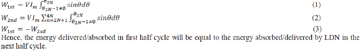
| The energy delivered/absorbed (by the LDN) at any nth interval is |
 |
CONTROL STRATEGIES
|
| PWM technique will cause extra losses due to high switching frequencies. For this reason, low-switching frequency control methods, such as selective harmonic elimination method, fundamental frequency switching method or active harmonic elimination method, can be used for the MLI control. |
| It is desired that the ac output voltage VO = Van follow a given waveform (e.g., sinusoidal) on a continuous basis by properly switching the power valves. The carrier based PWM technique fulfils such a requirement as it defines the on and off states of the switches of one leg of a VSI by comparing a modulating signal VA (desired ac output voltage) and a triangular waveform VC (carrier signal). |
SIMULATION RESULTS
|
| The performance of the topology is evaluated by simulating the circuit in MATLAB/Simulink. A Simulink model is developed for the single-phase version of the proposed topology. In this section to verify multilevel output for conventional and proposed system. The output voltage and current waveforms and their total harmonic distortion (THD) are analyzed. Also, the performance of the LDN and its energy consumption are investigated. Table II shows the parameters used for simulation. Fig:4&5 shows the conventional and proposed circuit diagram. The 13level output voltage is given in fig: 6(a), (b). The THD Verification for both system are given in fig:7(a),(b). |
CONCLUSION
|
| This paper has presented a new concept to increase the number of levels in a cascaded MLI. A single-phase bridge network is used to almost double the number of levels of the single phase cascaded MLI. The self-balancing topology is verified. The concept may be applied for both symmetric and asymmetric topologies. The results are compared with conventional methods and the has not only increased the levels but also maintained uniform power loading of the individual cell of the cascaded configuration. The operating principle of the circuit is explained. A detailed simulation is presented using MATLAB/Simulink. The THD= 3.99 for proposed topology which is better result compared with conventional system. |
Tables at a glance
|
 |
|
| Table 1 |
Table 2 |
|
Figures at a glance
|
 |
 |
 |
 |
| Figure 1 |
Figure 2 |
Figure 3 |
Figure 4 |
 |
 |
 |
| Figure 5 |
Figure 6 |
Figure 7 |
|
References
|
- Bai Z, Zhang Z, Zhang Y. A generalized three-phase multilevel current source inverter with carrier phase-shifted SPWM. In: Proceedings ofIEEE PECS; 2007.
- Beig AR, Narayanan G, Ranganathan VT. Modified SVPWM algorithm for three level vsi with synchronized and symmetrical waveforms.IEEE Trans. on Ind. El. 2007;54:486–93.
- Belbaz S, Kadjoudj M, Golea N. Analysis of the discontinuous PWM strategies applied to the VSI. In: Proceedings of IEEE intsymp oncomputational intelligence and intelligent informatics, Agadir (Morocco); 2007.
- Gupta AK, KhambadkoneAM. A space vector pwm scheme to reduce common mode voltage for a cascaded multilevel inverter. In: Proceedingsof 37th IEEE PESC ‘06, Jeju (Korea); 2006.
- H. Abu-Rub, J. Holtz, J. Rodriguez, and B. Ge, “Medium-voltage multilevel converters—State of the art, challenges, and requirements inindustrial applications,” IEEE Trans. Ind. Electron., vol. 57, no. 8, pp. 2581–2596, Aug. 2010.
- J. Dixon, J. Pereda, C. Castillo, and S. Bosch, “Asymmetrical multilevelinverter for traction drives using only one dc supply,” IEEE Trans.Veh.Technol., vol. 59, no. 8, pp. 3736–3743, Oct. 2010.
- J.J. Nedumgatt ,D.Vijayakumar,A.Kirubakaran,andS.Umashankar, “A multilevel inverter with reduced number of switches,” in Proceedings ofthe IEEE Students’ Conference on Electrical, Electronics and Computer Science (SCEECS ’12),pp.1–4, March 2012.
- Kanchan RS, Baiju MR, Mohapatra K, Ouseph P, Gopakumar K. Space-vector PWM signal generation for multilevel inverters using only thesampled amplitudes of reference phase voltage. IEE Electr Power Appl 2005;152:297–309.
- Kanchan RS, Gopakumar K, Kennel R. Synchronised carrier-based SVPWM signal generation scheme for the entire modulation rangeextending up to six-step mode using the sampled amplitudes of reference phase voltages. IEEE Elec Power App. 2007;1.
- Lin W. A new approach to the harmonic analysis of SPWM waves. In: Proceedings of IEEE intlconf on mechatronics and automation, Henan(China); 2006.
- M. D. Manjrekar, P. K. Steimer, and T. A. Lipo, “Hybrid multilevel power conversion system: A competitive solution for high-powerapplications,” IEEE Trans. Ind. Appl., vol. 36, no. 3, pp. 834–841, May/Jun. 2000.
- M. Malinowski, K. Gopakumar, J. Rodriguez, and M. A. Perez, “A survey on cascaded multilevel inverters,” IEEE Trans. Ind. Electron., vol. 57, no. 7, pp. 2197–2206, Jul. 2010.
- O.L.Jimenez,R.A.Vargas,J.Aguayo,J.E.Arau,G.Vela, and A. Claudio, “THD in cascade multilevel inverter symmetric and asymmetric,” inProceedings of the IEEE Electronics, Robotics and AutomotiveMechanics Conference(CERMA’11), pp. 289–295,November 2011.
- P. Palanivel and S. S. Dash, “Analysis of THD and output voltage performance for cascaded multilevel inverter using carrier pulse widthmodulation techniques,” IET Power Electronics, vol. 4, no. 8, pp. 951–958, 2011.
- S. Kouro,M.Malinowski, K. Gopakumar, J. Pou, L. G. Franquelo, B.Wu, J. Rodriguez,M. A. Perez, and J. I. Leon, “Recent advances andindustrial applications of multilevel converters,” IEEE Trans. Ind. Electron., vol. 57, no. 8, pp. 2553–2580, Aug. 2010.
- Wen X, Yin X.The SVPWM fast algorithm for three-phase inverters.In:Proceedings of the 8th IEEE international power engineering conference,Mandarin (Singapore); 2007.
|