Keywords
|
| Permanent-magnet synchronous motor (PMSM), low-resolution Hall Effect sensors, rotor position estimation, vector tracking observer, vector control of permanent magnet synchronous motor (PMSM). |
INTRODUCTION
|
| Permanent magnet (PM) synchronous motors are widely used in low and mid power applications such as computer peripheral equipments, robotics, adjustable speed drives, electric vehicles and other applications in a variety of automated industrial plants. In such applications, the motion controller may need to respond relatively swiftly to command changes and to offer enough robustness against the uncertainties of the drive system. among ac and dc drives, PMSM has received widespread appeal in motion control applications. The complicated coupled nonlinear dynamic performance of PMSM can be significantly improved using vector control theory where torque and flux can be controlled separately. The growth in the market of PM motor drives has demanded the need of simulation tools capable of handling motor drive simulations. |
| The proper vector-controlled operation absolutely depends on the accuracy of the rotor position information. Generally, this position information can be obtained from high-resolution sensors such as an incremental encoder or resolver mounted on a motor shaft. However, these sensors not only increase system cost, length, and size but also tend to reduce the system reliability [1]–[2]. In the case of employing the incremental encoder, an additional algorithm or procedure is necessary to obtain initial position at start-up. Various sensor less techniques have been developed, which are roughly categorized as techniques based on flux linkage [3], [4], and back electro motive force [5], [6], [7]. |
| Recently, several driving methods in the PMSM drives with Hall sensors have been proposed in the literature [1], [2], [8]–[12]. A vector-tracking observer with a feedforward input of the average rotor speed is developed to derive the high resolution rotor position is developed in this paper. The structure of the present observer in similar to the phase locked loop (PLL). This observer makes the position error to zero rapidly, and it also appropriately corrects the feedforward average speed, including intrinsic errors caused by sensors’ misalignments or speed variation. In addition, the feedforward input provides enough high-speed operating capability above the observer bandwidth. |
MATHEMATICAL MODELS
|
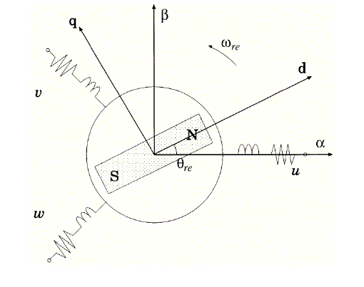
| In this section, circuit equations of PMSMs, which are used as mathematical models for sensorless control, are discussed on two kinds of coordinates. These coordinates are the rotating coordinate and the fixed coordinate, which are defined in Fig. 1. The circuit equation of surface permanent-magnet synchronous motor on the rotating coordinate is given as |
 |
| The first term on the right side of (1) is a voltage drop on the motor’s impedance, and the second term is an EMF term. |
| Transforming (1) on the fixed coordinate, (2) is derived |
 |
POSITION ESTIMATION ALGORITHMS
|
| In the last decades various algorithms have been developed to estimate the position and control the Permanent-magnet synchronous motor (PMSM). Some of them are linear extrapolation technique [8], and zeroth-order algorithm [9], [10]. These approaches based on average rotor speed. Recently some approaches to compensate the misalignment effect of Hall sensors have been introduced in [10]–[12]. |
| A. Permanent Magnet Synchronous Motor (Pmsm) Rotor Position Estimation With Average Rotor Speed |
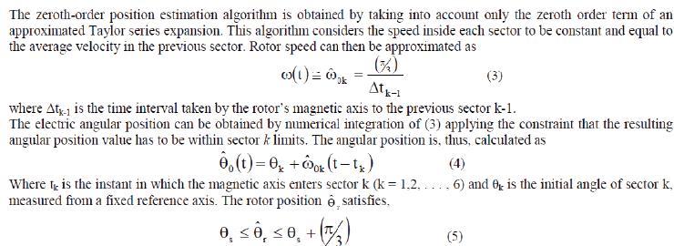
| The zeroth-order position estimation algorithm is obtained by taking into account only the zeroth order term of an approximated Taylor series expansion. This algorithm considers the speed inside each sector to be constant and equal to the average velocity in the previous sector. Rotor speed can then be approximated as |
 |
| The rotor speed can be approximated to a better degree by taking into account higher order terms of the Taylor series expansion. The first-order estimation algorithm is given as |
 |
| In (6), the first derivative is approximated as |
 |
| B. Effect Of Hall Sensors |
| If the Hall sensors are symmetrically aligned in the motor, the rotor position obtained may be considerably precise value at the steady-state operation. However, since variable speed operation or sensors’ misalignment may cause an excessive average-speed error due to the aforementioned intrinsic limitation, the estimation error inevitably appears in practice and causes some performance degradation such as current distortions and torque pulsation. |
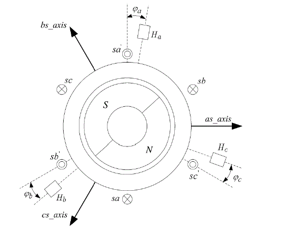
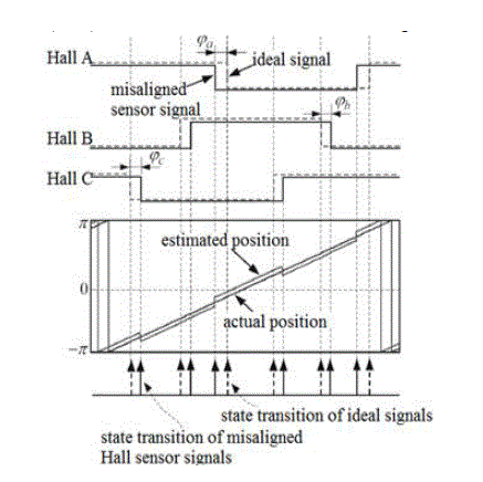
| A two-pole machine with misaligned Hall sensors is shown in Fig. 2, where ÃÂÃâ¢a, ÃÂÃâ¢b, and ÃÂÃâ¢c denote the angle differences between the actual stator magnetic axes and the practical placements of the corresponding Hall sensors. For instance, if the angle differences ÃÂÃâ¢a, ÃÂÃâ¢b, and ÃÂÃâ¢c are −15, 10, and 10 electrical degrees, respectively, the Hall sensor output signals and the resultant position estimation are shown in Fig. 3. In this figure, the rotor position is transiently distorted at each state transition of the misaligned Hall sensors’ signals. Although it is not identified in Fig. 3. The speed transient operation such as start-up, speed, and load change may also raise the position estimation error In the above methods in practice since each sector’s average speed may transiently change according to instantaneous or gradual change of the operating speed. |
PROPOSED VECTOR-TRACKING OBSERVER TO ESTIMATE THE ROTOR POSITION
|
| A different way to approach position estimation is to use a vector-tracking phase-locked loop. The same observer structure has already been used in [13] for Interior PM machine sensorless control. Furthermore, in [14], the vector tracking observer is proposed in order to estimate rotor position from a quantized rotating vector with limited resolution, examining the performance of a low-resolution encoder (1âÃâæ angular resolution) at steady state. The vectortracking observer is used here in a new and original fashion; startup and steady-state performances are evaluated. |
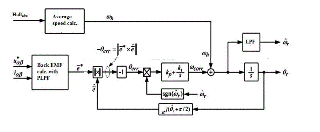
| The vector-tracking observer structure, Fig. 2, has two inputs: 1) a rotating vector containing position information and 2) a torque feedforward input to the mechanical model that provides position tracking above the observer bandwidth. |
| The proportional–integral–differential (PID) controller is used to force convergence. A rotating unit-vector based on the observed position is used as feedback to the phase detector. The estimated position is calculated using a latchedtorque model of a simple rotational system. A consideration of tuning the vector-tracking observer given the quantized nature of the Hall-effect sensors is that the sample rate of the motor position depends on the motor speed. Between transitions of the Hall sensor signal output, the observer relies on the feedforward torque command to estimate the rotor position. If the observer bandwidth is set too high, the resulting position estimate will be quantized. To solve this problem, the observer bandwidth should be speed dependent until a desired bandwidth is attained. |
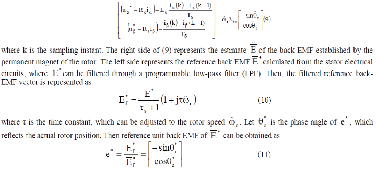
| Considering a digital control system with enough high sampling frequency, (2) can be expressed in discrete form. If the estimated rotor position, speed, and model parameters are the same as the actual values, the following equation can be obtained: |
 |
 |
 |
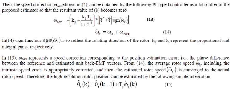
| Then, the speed correction ωcorr shown in (4) can be obtained by the following PI-typed controller as a loop filter of the proposed estimator so that the resultant value of (8) becomes zero. |
 |
| Where k is the sampling instant. |
PERFORMANCE OF THE PROPOSED VECTOR TRACKING OBSERVER
|
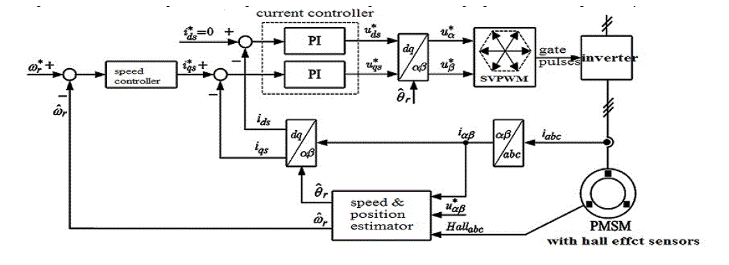
| The proposed vector-tracking position estimator is shown in Fig. 4. In practical use, the estimated speed ωr has to befiltered through an LPF to enhance the noise immunity as shown in Fig. 4. the general speed and decoupled current control loop in the synchronous reference frame with the position and speed estimator can be configured as shown in Fig.6 .The vector-tracking observer loop with feedforward input for the average speed ωh can be equivalently transformed to a second-order linear model as shown in Fig. 5. From Fig. 5(b), the transfer function for the estimated position can be derived as |
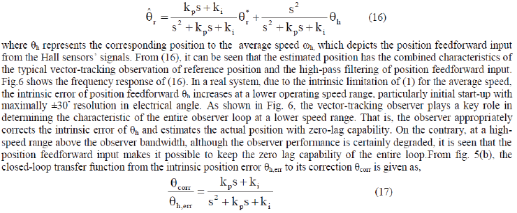 |
| where kp and ki are the proportional and integral gains of the PI controller, respectively. |
| estimating performance of θr relies on the dynamic performance of (12) determined by the design of only PI gains kp and ki. The instantaneous load torques can be used to compensate this error, where the load torques can be calculated in the reference and estimated synchronous frames . if the estimated load angle of (18) is added to the speed correction of (9),the proposed vector-tracking observer may enhance the position estimation performance by correcting the load induced error. The overall control scheme of the experimental drive is shown in Fig. 6. A drive for home appliance applications, composed of an axial-flux PM machine, a low cost full-bridge insulated gate bipolar transistor (IGBT) inverter in which the aforementioned control algorithm resides, has been built. The adopted machine has surfacemounted PM and slotless stator windings. thus its structure is highly isotropic and it exhibits very low inductance, which makes this machine a very good candidate to test the algorithms under investigation. |
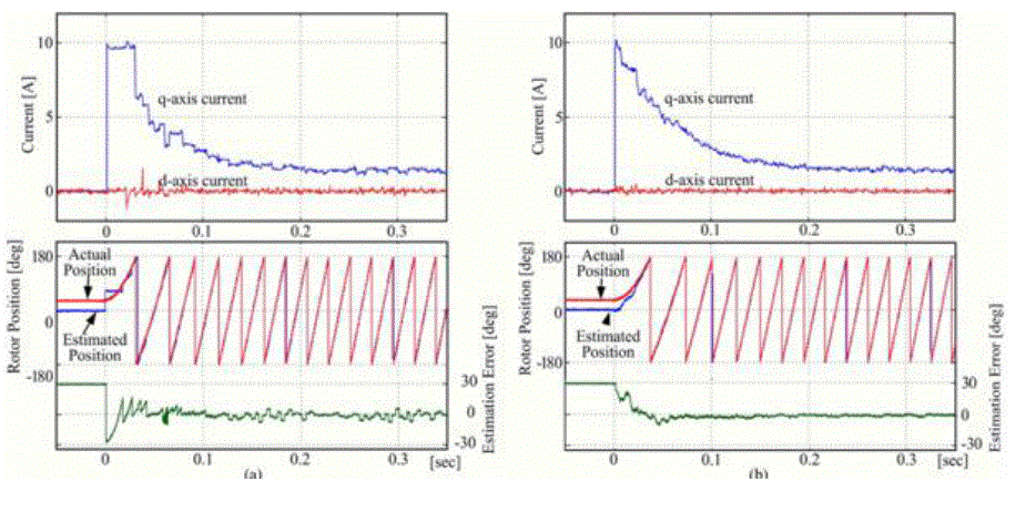
| Fig. 9. shows the start-up response of the speed change from standstill to 500 r/min, where the initial position was intentionally set to about 30 electrical degrees. The maximum position error allowed in the system using the Hall sensors With the average-speed-based approach in Fig. 9(a), although the magnitude of the position estimation error is estimation error transiently appears at the end of every 60âÃâæsector, and also, excessive ripples of d- and q-axis currents synchronously appear in accordance with the transient of the estimated position, since the average-speed error excessively increases at the speed transient. |
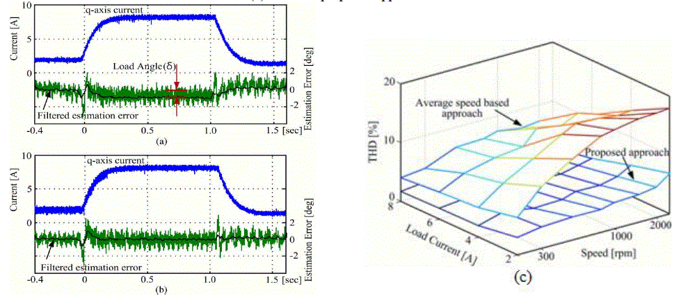
| Fig. 10(a) and (b) shows the resulting waveforms without and with the load angle compensation algorithm respectively. Fig. 10(c) shows The total harmonic distortions (THDs) of the stator phase current characterized under the different load current and speed conditions, where the THD is defined as |
 |
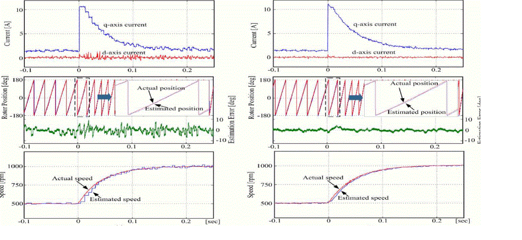
| where I1 and In are the fundamental component and nth-order harmonic component of the stator current, respectively. Figs. 11 show the step responses of the speed (from 500 to 1000 r/min at near no load). |
CONCLUSION
|
| In this paper an innovative brushless ac drive has been presented. Such a drive attempts to overcome some limitations of traditional brushless ac drives concerning the use of high resolution position sensors. The control algorithm’s most innovative feature is its adaptability to the whole speed range including startup. Three different types of speed and position Estimation algorithms have been presented and compared theoretically, in simulation. This structure allows the proposed approach to provide useful position information even at and around zero speed where the vector-tracking correction loop cannot correctly operate. Above zero speed, the proposed approach provides the high-resolution position information, where the position estimation error rapidly converges to zero regardless of the misalignment of Hall sensors and the excessive average-speed error, particularly speed transient operation Through the experiments at the steady-state, start up, speed transient, and load transient operations, the effectiveness and the dynamic performance of the proposed approach have been evaluated. |
Figures at a glance
|
 |
 |
 |
 |
 |
| Figure 1 |
Figure 2 |
Figure 3 |
Figure 4 |
Figure 5 |
 |
 |
 |
 |
 |
| Figure 6 |
Figure 7 |
Figure 8 |
Figure 9 |
Figure 10 |
|
References
|
- T. D. Batzel and K. Y. Lee, “Slotless permanent magnet synchronous motor operation without a high resolution rotor angle sens or,” IEEE Trans. Energy Convers., vol. 15, no. 4, pp. 366–371, Dec. 2000.
- A. Lidozzi, L. Solero, F. Crescimbini, and A. Di Napoli, “SVM PMSM drive with low resolution Hall-effect sensors,” IEEE Trans Power bElectron., vol. 22, no. 1, pp. 282–290, Jan. 2007.
- F. Genduso, R. Miceli, C. Rando, and G. R. Galluzzo, “Back EMF sensorless-control algorithm for high-dynamic performance PMSM,” IEEE Trans. Ind. Electron., vol. 57, no. 6, pp. 2092–2100, Jun. 2010.
- I. Boldea, M. C. Paicu, and G. D. Andreescu, “Active flux concept for motion sensorless unified ac drives,” IEEE Trans. Power Electron., vol. 23, no. 5, pp. 2612–2618, Sep. 2008.
- S. Morimoto, K. Kawamoto, M. Sanada, and Y. Takeda, “Sensorless control strategy for salient-pole PMSM based on extended EMF in rotating reference frame,” IEEE Trans. Ind. Appl., vol. 38, no. 4, pp. 1054–1061, Jul./Aug. 2002.
- Z. Chen, M. Tomita, S. Doki, and S. Okuma, “An extended electromotive force model for sensorless control of interior permanen t-magnet synchronous motors,” IEEE Trans. Ind. Electron., vol. 50, no. 2, pp. 288–295, Apr. 2003.
- D. Cascadei, G. Serra, A. Stefani, A. Tani, and L. Zarri, “DTC drives for wide speed range applications using a robust flux-weakening algorithm,” IEEE Trans. Ind. Electron., vol. 54, no. 5, pp. 2451–2461, Oct. 2007.
- B.-H. Bae, S.-K. Sul, J.-H. Kwon, and J.-S. Byeon, “Implementation of sensorless vector control for super-high-speed PMSM of turbo compressor,” IEEE Trans. Ind. Appl., vol. 39, no. 3, pp. 811–818, May/Jun. 2003.
- S. Morimoto, M. Sanada, and Y. Takeda, “High-performance current sensorless drive for PMSM and SynRM with only low-resolution position sensor,” IEEE Trans. Ind. Appl., vol. 39, no. 3, pp. 792–801, May/Jun. 2003.
- B. B. Philip, D. P. Steven, J. D. Bradley, and C. K. Andreas, “Compensation for asymmetries and misalignment in a Hall-effect position observer used in PMSM torque-ripple control,” IEEE Trans. Ind. Appl., vol. 43, no. 2, pp. 560–570, Mar./Apr. 2007.
- F. GiuliiCapponi, G. De Donato, L. Del Ferraro, O. Honorati, M. C. Harke, and R. D. Lorenz, “AC brushless drive with low-resolution Halleffect sensors for surface-mounted PM machines,” IEEE Trans. Ind Appl., vol. 42, no. 2, pp. 526–535, Mar./Apr. 2006.
- H. Kim, M. C. Harke, and R. D. Lorenz, “Sensorless control of interior permanent-magnet machine drives with zero-phase lag position estimation,” IEEE Trans. Ind. Appl., vol. 39, no. 6, pp. 1726–1733, Nov./Dec. 2003.
- T. Tesch, “Dynamic torque estimation in a sensor limited environment,” Ph.D. preliminary examination presentation, Dept. Mech. Eng., Univ.Wisconsin, Madison, Aug. 2000.
|