Keywords
|
| Brushless DC Motor (BLDC), Back EMF, Zero Crossing Detection (ZDC). |
INTRODUCTION
|
| Brushless DC (BLDC) motors are becoming widely used in variety of applications in industrial automation and consumer appliances because of their higher efficiency, silent operation, compact form, reliability and low maintenance. In recent times a lot of research on sensorless control technique for BLDC motor has been conducted. |
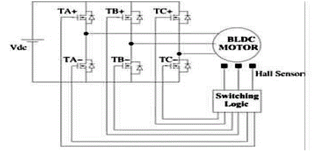
| The structure of a BLDC motor is shown in Fig. 1. BLDC drive system consists of a BLDC motor, control circuit and sensor for position information. |
| In a BLDC motor drive system position information is obtained from the Hall Effect sensor output. |
| Previously Rotor position information is determined by indirectly sensing the back emf from one of the three motor terminal voltages of three phase motor. The two typical control methods for BLDCM is square wave control method and the other is sinusoidal current control method. The accuracy for the position information is different between two control methods. In this paper proposed technique is the “Back EMF ZCD” is used to determine the Rotor Position Detection Technique for Sensor less BLDC Motor control. Back EMF is obtained from the supply, with the voltage divider connected with low pass filters and comparator circuit. When this Back EMF is send to zero crossing detector circuit a positional pulse used for rotor position detection is obtained. The Positional Pulse is compared with the hall pulse and their phase difference is obtained. When the motor is in standstill conditions the back EMF will be zero, so rotor position cannot be determined. To determine the rotor position at both in standstill and running conditions back EMF ZCD method is used. |
SENSORLESS OPERATION OF BLDC
|
| Brushless dc (BLDC) motors, with their trapezoidal electromotive force (EMF) profile, requires six discrete rotor position informations for the inverter operation. These are typically generated by Hall- effect switch sensors placed within the motor. However, it is a well-known fact that these sensors have a number of drawbacks. They increase the cost of the motor and need special mechanical arrangements to be mounted. Further, Hall sensors are temperature sensitive, and hence limit the operation of the motor. They could reduce system reliability because of the extra components and wiring. So sensor less method is the reliable method used in harsh environments. There are two independent methods for determining the Hall configuration. The selection of which method to use will depend on the information provided. |
| 1. Hall Based Commutation Sequence Provided. |
| 2. Back EMF Waveforms. |
| Hall Based Commutation Sequence Provided: |
| This method is the straight forward and requires the least amount of effort on the part of the user. This information is usually provided in the form of a diagram or table and may have different titles such as “Block Commutation” or “Brushless DC Motor Timing Diagram”. |
| Some of these diagrams represent motor phase voltage during trapezoidal (six-step) commutation. |
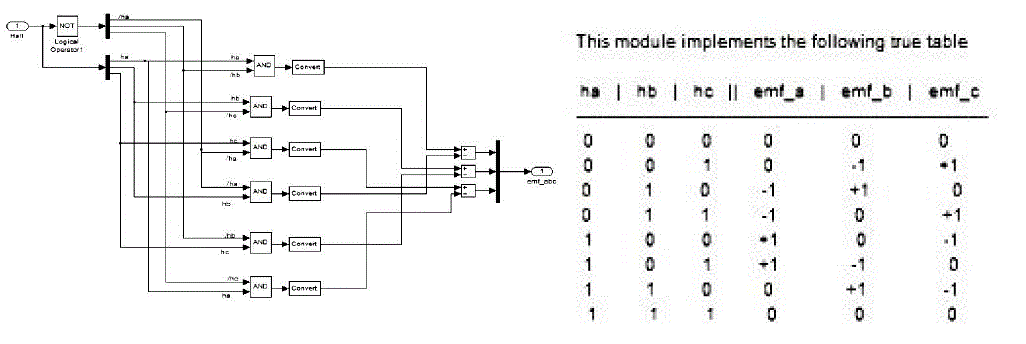
| Other tables may represent the state of the high-side and low-side MOSFETs of the half-bridge amplifiers for all three phases during trapezoidal commutation. Either method conveys adequate information about driving the motor phases based on Hall Effect sensor states. The relationship between the Hall Effect sensors themselves is always consistent. In other words the Hall Effect sensor sequence seen in can be found in all motors with 120-degree Hall Effect sensors when the motor rotates. However, the direction of rotation, CW or CCW, necessary to produce this relationship can vary across different motors. Very often the binary state of the three Hall Effect sensors will be combined to create a 3- bit binary word. |
| The mapping between the Hall states and the three-bit word. Below the binary word representation in are tables that represent the states of the MOSFETs of the half-bridges . Every Hall state has a unique half-bridge state defined as follows: |
| A+ = Phase A high side MOSFET closed, A- = Phase A low side MOSFET closed |
| B+ = Phase B high side MOSFET closed, B- = Phase B low side MOSFET closed |
| C+ = Phase C high side MOSFET closed, C- = Phase C low side MOSFET closed |
| If the state of a MOSFET for a particular Hall state is not defined then it is assumed to be 0pen. For example during Hall state 1-0-1, MOSFETs A-, B+, C+ and C- are all open. Below the table of MOSFET states in is a diagram of the relative voltages through each motor phase based on the Hall states (and subsequent MOSFET states). For instance in Hall state 1- 0-1, the path of the current begins at the voltage source, flows through the high side MOSFET of phase A, through motor winding A, through motor winding B, through the low side MOSFET of phase B, and finally to the ground plane. |
PROPOSED DIRECT BACK EMF SENSING
|
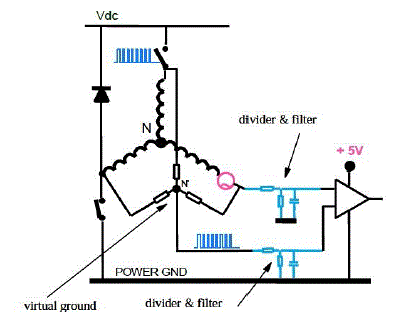
| The phase back EMF voltage is referred to neutral point of the motor. Since the center point of the motor is typically not available, the commonly used method reconstructs the neutral voltage information. Figure 2 shows the detection circuit based on motor virtual neutral voltage. Voltage dividers and low pass filters are necessary to process the signals. The low pass filter will introduce a phase delay for the zero crossing of the phase back EMF. The first problem with this scheme is low signal/noise ratio at low speed, since the back EMF amplitude is directly proportional to the motor speed. The second problem is that the low pass filter at high speed introduces too much phase delay. Consequently, the conventional back EMF sensing method is only good for narrow speed range. |
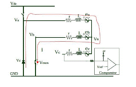
| For BLDC drive, only two out of three phases are excited at any instant of time, leaving the third phase floating. |
| For example, when phase A and phase B conduct current, phase C is floating. This conducting interval lasts 60 electrical degrees, which is called one step. A transition from one step to another Sensor less Control of BLDC Motor. Different step is called commutation. So totally, there are 6 steps in one cycle. The first step is AB, then to AC, to BC, to BA, to CA, to CB and then just repeats this pattern. |
| Usually, the current is commutated in such way that the current is in phase with the phase back EMF to get the optimal control and maximum torque/ampere. The commutation time is determined by the rotor position. Since the shape of back EMF indicates the rotor position, it is possible to determine the commutation timing if the back EMF is known. The phase current is in phase with the phase back EMF. If the zero crossing of the phase back EMF can be measured, we will know when to commutate the current. |
| As mentioned before, at one time instant, since only two phases are conducting current, the third winding is open. This opens a window to detect the back EMF in the floating winding. The terminal voltage of the floating winding is measured. This scheme needs the motor neutral point voltage to get the zero crossing of the back EMF, since the back EMF voltage is referred to the motor neutral point. The terminal voltage is compared to the neutral point, and then the zero crossing of the back EMF can be obtained. In most cases, the motor neutral point is not available. |
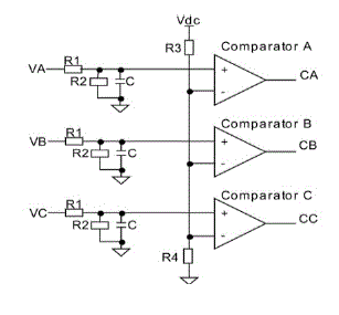
| When virtual neutral point is built by resistors. This scheme is quite simple. It has been used for a long time since the invention. Because of the PWM drive, the neutral point is not a standstill point. The potential of this point is jumping up and down. It generates very high common mode voltage and high frequency noise. So we need voltage dividers and low pass filters to reduce the common mode voltage and smooth the high frequency noise, For instance, if the dc bus voltage is 300 V, the potential of the neutral point can vary from zero to 300 V. The allowable common mode voltage for a comparator is typically a few volts, i.e. 5 V. Obviously, the voltage divider will reduce the signal sensitivity at low speed, especially at start-up where it is needed most .On the other hand, the required low pass filter will induce a fixed delay independent of rotor speed. As the rotor speed increases, the percentage contribution of the delay to the overall period increases. This delay will disturb current alignment with the back EMF and will cause severe problems for commutation at high speed. Consequently, this method tends to have a narrow speed range. In the past, there have been several integrated circuits, which enabled the sensor less operation of the BLDC. A few other schemes for sensor less BLDC motor control were also reported in the literature. The back EMF integration approach has the advantage of reduced switching noise sensitivity and automatically adjustment of the inverter switching instants to changes in the rotor speed. The back EMF integration still has accuracy problems at low speeds the rotor position can be determined based on the stator third harmonic voltage component. The main disadvantage is the relatively low value of the third harmonic voltage at low speed. In, the rotor position information is determined based on the conducting state of freewheeling diodes in the unexcited phase. The sensing circuit is relatively complicated and low speed operation is still a problem The proposed back emf detection method describes that, instead of detecting the zero-crossing point (ZCP) of the non-excited motor back electromagnetic force (EMF) or the average motor terminal to neutral voltage, the true zero-crossing points of back EMF are extracted directly from the supply with simple RC circuits and comparators. In contrast to conventional methods, the neutral voltage is not needed and the diode freewheeling currents in the nonconducted phase are eliminated completely; therefore, the commutation signals are more accurate and insensitive to the common-mode noise. As a result, the proposed method makes it possible to achieve good motor performance over a wide speed range and to simplify the starting procedure. |
IMPLEMENTATION OF PROPOSED STRATEGY
|
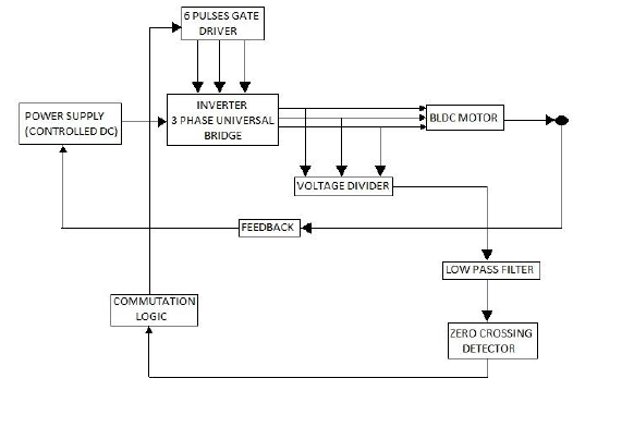
| A power supply is given to the inverter. The three phase output of the inverter is applied to the motors stator windings. From the supply, voltage divider is connected, with the RC low pass filter and a zero crossing detector circuit to produce the back EMF for three phases. Low pass filter is a filter that passes low frequency signals but attenuates higher frequency signals. |
| The actual amount of attenuation for each frequency varies from filter to filter. The low pass filter has been designed for a frequency of 300 Hz. A zero crossing detector literally detects the transition of a signal waveform from positive and negative, ideally providing a narrow pulse that coincides exactly with the zero voltage condition. The Back EMF signals are send to the zero crossing detector the positional pulse are produced. A voltage divider (also known as a potential divider) is a simple linear circuit that produces an output voltage (Out) that is a fraction of its input voltage (Vin). |
| Voltage division refers to the partitioning of a voltage among the components of the divider. To drive the BLDC motor, an electronic commutation circuit is required. The widely used commutation methods for the BLDC motor are trapezoidal (or six-step), sinusoidal, and field oriented control (FOC) (or vector control). The sinusoidal drive scheme replaces the flat peak of the trapezoid with a sinusoidal waveform that matches more closely the back-EMF. It is necessary to overlap the commutation of phases, selectively firing more than one pair of power switching devices at a time. |
SIMULATION RESULTS
|
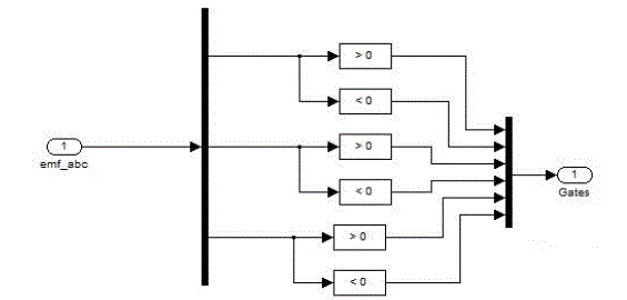
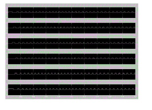
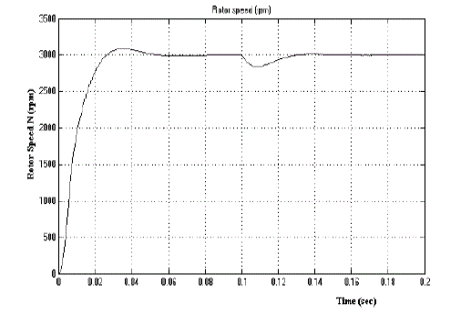
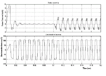
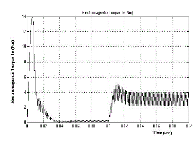
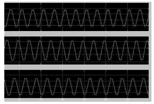
| A three BLDC motor is fed to the to the inverter bridge and it is connected to controlled voltage source The inverter gates signals are produced by decoding hall effect signals. The three phase output of the inverter is applied to the motors stator windings. From the supply voltage divider is connected, with the RC low pass filter and a compare to zero circuit to produce the back emf for three phases. After simulating the circuit on the Matlab/Simulink, Motor rotor speed. Electromotive force, stator current and electromotive torque are shown in fig.11,12 and 13. |
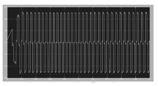
| As shown in fig13 all these waveform contains spikes, the circuit with a RC low pass filters is designed and as a result an improved waveform of back emf is obtained as shown in fig.14 |
CONCLUSION AND FUTURE TRENDS
|
| A simple approach of detecting back EMF using comparator and RC filter is defined. This method provides an improved version of the back EMF. Rotor Position is determined by Back EMF ZCD. In this paper it is shown that BLDC motor is a good choice in automotive industry due to higher efficiency, higher power density and higher speed ranges compare to other motor types. BLDC motor model with improved back emf and rotor position detection method is presented in this paper. The proposed model is simulated in MATLAB / SIMULINK. Simulation results under no load and load conditions are showing proper performance of model. Output characteristics and simplicity of model make it effectively useful in design of BLDC motor drives with different control algorithms in different applications. |
Figures at a glance
|
 |
 |
 |
 |
 |
| Figure 1 |
Figure 2 |
Figure 3 |
Figure 4 |
Figure 5 |
 |
 |
 |
 |
 |
| Figure 6 |
Figure 7 |
Figure 8 |
Figure 9 |
Figure 10 |
 |
 |
 |
 |
| Figure 11 |
Figure 12 |
Figure 13 |
Figure 14 |
|
References
|
- P. P. Carney and J. F Watson, “Review of position-sensor less operation of permanent-magnet machines,” IEEE Trans. Ind. Electron., vol. 53, no. 2, pp. 352–362, Apr. 2006.
- C.-H. Chen and M.-Y. Cheng, “New cost effective sensor less commutation method for brushless dc motors without phase shift circuit and neutral voltage,” IEEE Trans. Power Electron., vol. 22, no. 2, pp. 644–653, Mar.2007
- C.-G. Kim, J.-H.Lee, H.-W.Kim, and M.-J. You, “Study on maximum torque generation for sensor less controlled brushless DC motor with trapezoidal back EMF,” IEE Proc.-Electro. Power Appl., vol. 152, no. 2, pp. 277–291, Mar. 2005 4. J.X. She and S. Iwasaki, “Sensor less control of ultrahigh-speed PM brushless motor using PLL and third harmonic back EMF,” IEEE Trans. Ind. Electron., vol. 53, no. 2, pp. 421–428, Apr. 2006.
- P. Damodharan, R. Sandeep, and K. Vasudevan, “Simple position sensor less starting method for brushless DC motor,” IEEE Electro. Power Appl., vol. 2, no. 1, pp. 49–55, Jan. 2008.
- D. K. Kim, K. W. Lee, and B. I. Kwon, “Commutation torque ripple reduction in a position sensor less brushless dc motor drive,” IEEE Trans. Power Electron., vol. 21, no. 6, pp. 1762–1768, Nov. 2006
- C.-G. Kim, J.-H.Lee, H.-W.Kim, and M.-J. Youn, “Study on maximum torque generation for sensor less controlled brushless DC motor with trapezoidal back EMF,” IEE Proc.-Electro. Power Appl., vol. 152, no. 2, pp. 277–291, Mar. 2005.
- J. H. Song and I. Choy, “Commutation torque ripple reduction in brushless dc motor drives using a single dc current sensor,” IEEE Trans. Power Electron., vol. 19, no. 2, pp. 312–319, Mar. 2004.
- S. Wu, Y. Li, X. Miao, “Comparison of Signal Injection Methods for sensor less control of PMSM at Very Low Speeds”, IEEE Power Electronics Specialists Conference, PESC 2007, June 2007 pp. 568 – 573.
- M. Eskola, H. Tuusa, “Sensor less Control of Salient Pole PMSM Using a Low –Frequency Signal Injection”, European Conference on Power Electronics and Applications, Sept. 2005,
- S. Ogasawara, H. Akagi, “An Approach to Real-Time Position Estimation at Zero and Low Speed for a PM Motor Based on Saliency”, IEEE Transactions on Industry Applications, Vol. 34, No. 1, Jan./Feb 1998, pp. 163-168
- JoohnSheok Kim, Seung Ki Sul, “New Stand-Still Position Detection Strategy for PMSM Drive without Rotational Transducers”, Conference Proceedings of the Ninth Annual Applied Power Electronics Conference and Exposition, APEC '94., Vol. 1, 13-17 Feb. 1994, pp.363 – 369.
|