Keywords
|
| WiMAX/WLAN antennas, coplanar wave guide antennas, return loss, VSWR |
INTRODUCTION
|
| Recently, some practical requirements such as multiband operation and miniaturized size for current antenna design in wireless communication systems have attracted high attention. For short- and long-range applications, many antenna designs suitable for wireless local area network (WLAN: 2.4-2.483 GHz, 5.15-5.35 GHz and 5.725-5.85 GHz) and worldwide interoperability for microwave access (WiMAX 2.5-2.69 GHz, 2.7-2.9 GHz (India), 3.3-3.8 GHz and 5.25- 5.85 GHz) operation have been studied [1-8]. The printed planar wide-slot antennas based on more than two resonant modes to generate a wider operating band were initially proposed to meet the applications for both WiMAX and WLAN systems. However, in these designs, lower performance of interference suppression was mainly due to the absence of band pass filter. To address this issue, several recent antennas capable of reducing frequency collision and therefore enhancing system performance have been developed with open or symmetric slots for WiMAX and WLAN operation [3-8]. As for practical applications, all these designs have complicated structure that results in more cost for antenna fabrication. There are several advantages of WIMAX which include easy extension to suburban and rural areas and much wider coverage than WiFi hotspots, easy installation and also it is faster than broadband services, and advantages of WLAN includes flexibility: within radio coverage, nodes can communicate without further restriction, planning: wireless ad hoc networks allow for communication without planning. Wired networks need wiring plans, WLAN products are of very low cost. |
| Now a day’s, CPW fed antennas have many attractive features like low radiation loss, less dispersion, less coupling between adjacent components ,easy integration for monolithic integrated circuits, so these types of antennas have recently become more and more attractive, one of the main issue with CPW fed slot antennas is to provide an easy impedance matching to the CPW line. CPW allows shunt and series connection on the same side of the substrate and avoid the use of via holes. CPW provides the benefits of good impedance matching, omnidirectional patterns and wider bandwidth. It is easy of fabrication comparing to Microstrip line. These advantages of the CPW make it a preferable way to feed antenna and to integrate with active devices. |
| In this letter we propose a novel antenna that is simple and well suited for WIMAX and WLAN operation. Compared with those designs shown in [3-8], the antenna which has a simple structure is easy to fabrication to be embedded inside the portable devices for achieving WiMAX and WLAN operation. |
| This antenna has a simpler geometry structure with Two c-shapes and one T-shape had less parameters. And the proposed antenna is successfully designed with a compact aperture area of 33 X 19.5mm2. As will be seen, an operation of bandwidths of 300 MHz and 700 MHz in the frequency ranges 2.7GHz to 2.9 GHz and 5.15GHz to 5.85 GHz respectively. And these frequency bands are used by IEEE802.16a. , IEEE802.11a respectively. |
| The commercial simulator IE3D is used to simulate and optimize the proposed antenna, relative omnidirectional and stable radiation patterns are achieved. |
II.ANTENNA DESIGN
|
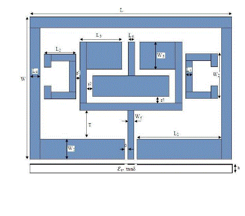
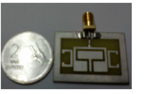
| The schematic diagram of the antenna is shown in Fig. 1. This antenna consists of dielectric constant εr= 4.4, loss tangent tanδ of 0.02, and substrate thickness h=1.6mm, and the other dimensions are given below. W=25mm W1 =3.5mm, W2 =8.5mm , W3 = 5 mm, Wf =1.0mm; L=35mm L1=16.5 mm, L2=6 mm, L3=6.5 mm, L4=2.0 mm, L5 =1.0 mm, L6 = 2.0 mm. The spacing between the edge of the ground plane and end of the patch terminal, extrusion depth, T = 4.5 mm and gap between centre strip conductor and ground plane is G=0.5mm, g1=0.5mm, g2=1mm, g3=1mm. The excitation of the antenna is formed by a simple two C-shapes and one T- shape as shown in Fig.1. |
| B. Radiation Patterns with Azimuthal Angles |
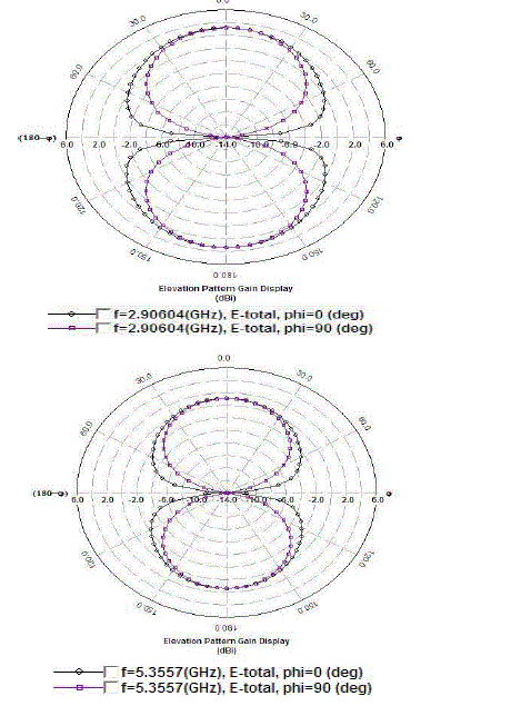
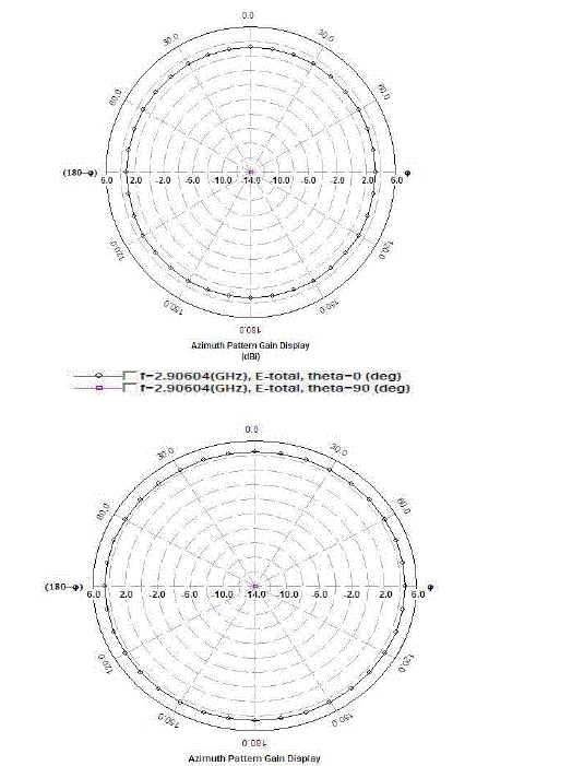
| The above figures shows the simulated radiation patterns with elevation and azimuthal at different frequencies by using Zeland IE3D software. The simulated radiation patterns of antenna in the E-plane (xz- plane) and H-plane (YZ-plane) for two different frequencies 2.9GHz, 5.35GHz are shown in Fig.3 and Fig.4, respectively. C. Return loss, VSWR, Gain |
| The return loss, gain, VSWR is obtained at the time of simulation. We have taken cells per wavelength as 20 and good radiation patterns are achieved. The curves of return loss, VSWR and gain are obtained for the designed antenna is shown below. |
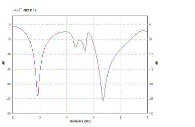
| From Fig.5 we can observe the two frequency ranges 2.71GHz to 2.9GHz and 5.15GHz to 5.85GHz, for return loss lower than -10 dB have maximum return losses -24 dB and -26 dB at 2.9GHz and 5.35 GHz respectively. The |
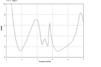
| first band is used for WiMAX application and second band is used for WLAN application. So this antenna can be used for dual band applications. it is clear from the Fig 5 that the simulated voltage standing wave ratio of the antenna is less than 2 for dual bands which covers the WIMAX/WLAN application Hence it is seen that at both the resonant frequencies (2.9GHz/5.35GHz) the VSWR is 1.1 which is nearly equal to ideal value 1. |
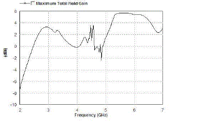
| Finally the antenna gain is observed and displayed in Fig.7. The antenna gain is observed 3.2dBi at 2.9GHz owing to high return loss of -24dB and the gain is above 5.5dBi at 5.35GHz owing to high return loss of -26dB. We can also observe the decrease in gain below 1dBi owing to lower return loss. |
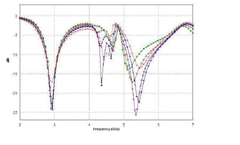
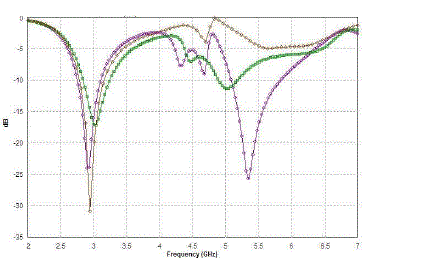
| From Fig.7 we can observe different curves for different T (extrusion depth) values. As we are mainly focusing for particular applications, it is observed from the table, the designed antenna at T=4.5 mm works for WiMAX/ WLAN applications |
| The differences in return loss are shown in above keeping T and C-shape. In case of removing C-shapes and Tshape the WLAN/WiMAX disappears. By changing the length and width of C-shapes and T-shape we observed that the resonant frequency is not in the intended application. Comparing the above two graphs we have taken extrusion depth as T=4.5mm and two C-shapes, one T-shape where we obtained the perfect results. The results shown have bandwidths of 2.71GHz to 2.9GHz and 5.15GHz to 5.85GHz which are used for WiMAX/WLAN applications of IEEE 802.16a and IEEE 802.11a. |
V.CONCLUSION
|
| The designed antenna performed well over the WiMAX (2.71to2.9 GHz) /WLAN (5.15 to 5.85 GHz) frequencies and consists of simple layout and compact aperture size (33 X 19.5mm2). Advantages of this antenna are easy to construct, simple structure, and low cost. This antenna is used for dual band applications. The fundamental parameters of the antenna such as return loss, VSWR, gain, radiation patterns are obtained. All parameters meet the acceptable antenna standard and the satisfactory results are observed. In this paper we have studied the effects of extrusion depth, number of C- shapes, and T-shapes, length and width. |
ACKNOWLEDGMENT
|
| The Authors would like to thank Prof. R.V. Rajkumar, Vice-chancellor, RGUKT and Prof. Ibrahim Khan, Director, RGUKT for their constant support and encouragement on this work |
Tables at a glance
|
 |
| Table 1 |
|
| |
Figures at a glance
|
 |
 |
 |
 |
 |
| Figure 1 |
Figure 2 |
Figure 3 |
Figure 4 |
Figure 5 |
 |
 |
 |
 |
| Figure 6 |
Figure 7 |
Figure 8 |
Figure 9 |
|
| |
References
|
- Yu-Chen Chang, Hong-Twu Chen, and Hsin-Cheng Su “Novel Design of Printed Monopole Antenna for WLAN/WiMAX Applications,” IEEE Antennas and Propagation Society International Symposium pp.3281-3284, 2007.
- Chia-Yang Mo and Jui-Ching Cheng, “A Novel Tri-band Dual-port Co planar Waveguide-Fed Slot Loop Antenna for WLAN and WiMAXApplications,” IEEE Asia Pacific Microwave Conference, pp. 1-4, 2008.
- Deepti Das Krishna, M. Gopikrishna, C. K. Anandan ,P.Mohanan. “CPW-Fed Koch Fractal Slot Antenna for WLAN/WiMAXApplications,” IEEE Antennas and Wireless Propagation Letters, vol.7 pp.389-392, 2008.
- M. Roshanaei R. Faraji-Dana, “A New Quad-Band CPW- Fed Stacked Antenna for Wireless LAN Applications,” Int. Conf. onElectromagnetics in Advanced Application,pp.535-538, 2007.
- Chien-Yuan Pan, Tzyy-Sheng Horng, Wen-Shan Chen Chien-Hsiang Huang, “Dual Wideband Printed Monopole Antenna forWLAN/WiMAX Applications”, IEEE Antennas and Wireless Propagation Letter, vol.6, pp.149-151, 2007.
- Hsien-Wen Liu Chia-Hao Ku, and Chang-Fa Yang,, “Novel CPW-fed Planar Monopole Antenna for WiMAX/WLAN Applications,” IEEEAntennas and Wireless Propagation Letter, vol.9, pp.240-243, 2010.
- TuanjaiArchevapanich and NoppinAnantrasirichar,“Inversed E-Shape Slot Antenna for WLAN Applications,”Int. Conf. on Control, Automation and Systems. pp.2854-2857, 2007
- 8. Yen-Chi Shen, Yu-Shin Wang, and Shyh-Jong Chung, “A Printed Triple-Band Antenna for Wi-Fi and WiMAX Applications,” IEEEAsia Pacific Microwave Conference,pp.1715-1717, 2006.
- SuwatSakulchat, AmnoiyRuengwaree, “Dual Band Microstrip Antenna with Triangular Tuning Stub for Propagation and EM Theory, pp.377-380, 2008.
- M. Midrio, S. Boscolo, F. Sacchetto, C. G. Someda, A. D.Capobianco, and F. M. Pigozzo, “Planar, Compact Dual- BandAntenna for Wireless LAN Applications” IEEE Antennas and Wireless Propagation Letters, vol.8 pp.1234-1237, 2009.
- Yi-Chieh Lee, Jwo-Shiun Sun, Min-Hsiang Hsu, and Ren- Hao Chen “A New Printed Slot Loop Antenna with Tunable Strips for 2.4-and 5-GHz Wireless Applications,” IEEE Antennas and Wireless Propagation Letters, vol.8,pp356-358,2009
|