Keywords
|
| Induction motor, direct torque control (DTC), Adjustable Speed Drives (ADS), MATLAB / SIMULINK, total harmonic distortion, modeling, and common mode voltage. |
INTRODUCTION
|
| The standard in those drives are Induction Motors (IM) are widely used in application such as pumps, fans, elevators, electrical vehicles, heating, ventilation and air-conditioning (HVAC), robotics, wind generation systems, ship propulsion etc. [1]-[2]. Previously, DC machines were preferred for variable speed drives. However, DC motors have disadvantages of higher cost, higher rotor inertia and maintenance problem with commutator and brushes. In addition they cannot operate in dirty and explosive environments. Therefore, in last three decades the DC motors are progressively replaced by AC drives. The responsible for those result are development of modern semiconductor devices, especially power Insulated Gate Bipolar Transistor (IGBT) various speed control schemes such as Field oriented control (FOC) and direct torque control (DTC) [3]. The first vector control method of induction motor was Field Oriented Control (FOC) presented by K. Hasse [4] and F. Blaschke [5] in early of 70s. the Matlab and Simulink packages were used to perform simulations on a number of control schemes. These schemes were Field Oriented Control, Direct Torque Control (DTC), DTC using Space Vector Modulation, and a novel Direct Torque Control (DTC) with Minimal Common mode voltages and Torque Ripple [6]-[7]. The novel Direct Torque Control (DTC) using Space Vector Modulation was chosen based on its low current distortion. One of the most wide spread techniques for high performance electrical drives with induction machines in industry applications is a novel direct torque control (DTC) based on voltage vectors [8]-[9]. However, its inherent fast switching frequency has, among other effects, the drawback of generating high level common mode voltage variations with resulting high frequency common mode currents flowing to the ground through the parasitic capacitances between the different parts of the drive and the ground, thus causing the drive itself to be less reliable. Another approach consists in limiting the cause of the common mode disturbance by proper selection of the switching pattern of the inverter [10]. In such an approach a new pulse width modulation (PWM) strategy is introduced to reduce the common-mode voltages in PWM inverter motor drives by the use of only three inverter states in each sector of the inverter hexagon, which are alternatively either only even or only odd voltage vectors. It permits only six variations of the common-mode voltage in each period of the fundamental of the voltage waveform at steady state and results in fewer emissions. In any case a voltage space vector is created by computing the time intervals during which each inverter state is applied. In this paper, the proposed novel DTC algorithm reduces the common mode emissions of the drive in each of the six sectors of the inverter hexagon, without using any null vector. This approach permits the common mode emissions to be reduced at the expense of a slight increase of the torque and flux ripples as well as of the harmonic content of the voltage and current wave forms. The numerical simulations have been carried out by using MATLAB/SIMULINK software packages. |
MATHEMATICAL MODELING OF INDUCTION MOTOR
|
| To study the dynamic performance of the machine model, a motor model has been developed in a stationary reference frame by using equations (1)-(3). |
 (1) (1) |
| The stator and rotor flux linkages in the stator reference frame are defined as, |
 (2) (2) |
| The electromagnetic torque of the induction motor in stator reference frame is given by |
 (3) (3) |
| By using the above equations the induction motor model is developed in stator reference frame. The simulation of induction motor has been carried out in the MATLAB-SIMULINK environment under the no-load condition. |
PROPOSED DIRECT TORQUE CONTROL
|
| The electromagnetic torque of a three-phase induction motor can be written as, |
 (4) (4) |
 |
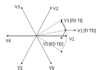
| In this new DTC algorithm when the stator flux space vector lies in the Kth sector, if an increase in the flux is required ,then the Kth voltage vector is applied , otherwise , if an increase in the torque is required , then the (k+2)th voltage vector is applied. The vector diagram given in Fig.1shows the voltage vector selection when the stator flux vector ? s lies in the first sector and one of the voltage sectors V1, V3 and V5is applied. Actually, when the stator flux linkage lies in the kth sector, the application of the kth voltage vector produces an increase in the flux amplitude and a slight decrease of the electromagnetic torque the application of the (K+2)th voltage vector produces a slight decrease in the flux amplitude and an increase in the electromagnetic torque, while the application of (K-2)th voltage vector produces a slight decrease in the flux amplitude and a decrease in the electromagnetic torque. |
| The Switching vector table for proposed DTC is shown in Table 1. In particular the application of V1 causes a strong increase of the flux amplitude and a slight decrease of the torque, the application of V3causes a slight decrease of the flux amplitude strong increase of the torque and finally the application of V5 causes a strong decrease of the flux amplitude and a strong decrease of the torque. With such a control law, flux control must be performed before torque control, otherwise the machine cannot be magnetized at zero speed without load torque (zero speed operation), or at steady state gets demagnetized rapidly after a series of torque commands. |
| Moreover, it is apparent that a reduction of the flux always causes the torque to be varied. This means that when the flux lies in the odd (even) sector only odd (even) voltage vectors are employed. Each communication of the commonmode voltage variation appears only when the stator flux linkage goes from one sector to the adjacent one. Moreover, at each sector crossing, the common-mode voltage variation is the minimum achievable, equal in magnitude to Vdc/3. |
COMMON MODE VOLTAGES
|
| For the most common two-level voltage source inverter there are three switching variables a, b, c one per phase of the inverter. Every terminal of the induction motor will be connected to the pole of one of the inverter legs, and thereby, either to the positive dc bus or the negative dc bus. The CMV is the potential of the star point of the load with respect to the Centre of the dc bus of the VSI. The CMV generated by a star connected three phase electric machine is given by, |
 (5) (5) |
| Where sAo V sBo V and sCo V are the inverter output phase voltages referred to the medium point of the dc-link bus, which in this case is assumed to be connected to ground. The lack of this connection to ground causes an additional voltage term. If the machine is supplied by a symmetric sinusoidal three-phase voltage, Vcom is instantaneously equal to 0. However, when the machine is supplied by an inverter the common mode voltage is always different from zero and its instantaneous value can be computed on the basis of the dc-link voltage (Vdc) and the switching pattern of the inverter. |
DIRECT TORQUE CONTROLLED BASED INDUCTION MOTOR DRIVE
|
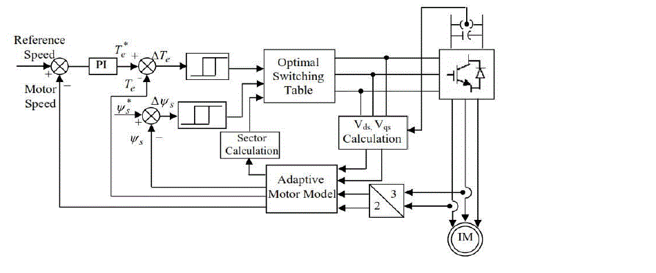
| The Fig.2 shows the block diagram of conventional direct torque controlled induction motor drive. There are two hysteresis control loops, one for the control of torque and other for the control of stator flux. The flux controller controls the machine operating flux to maintain the magnitude of the operating flux at the rated value till the rated speed. Torque control loop maintains the torque close to the torque demand. Based on the outputs of these controllers and the instantaneous position of stator flux vector, a proper voltage space vector is selected. Based on the outputs of hysteresis controllers and position of the stator flux vector, the optimum switching table will be constructed. This gives the optimum selection of the switching voltage space vectors for all the possible stator flux linkage space vector positions. If a stator flux increase is require then SΨ=1; if a stator flux decrease is required then SΨ = 0 The digitized output signals of the two level flux hysteresis controller are defined as, |
 |
| If a torque increase is required then ST=1 if a torque decrease is require then S T=-1 and if no change in the torque is required then ST=0 The digitized output signals of the three level torque hysteresis controller for the anticlockwise rotation or forward rotation can be defined as, |
 |
SIMULATION RESULTS
|
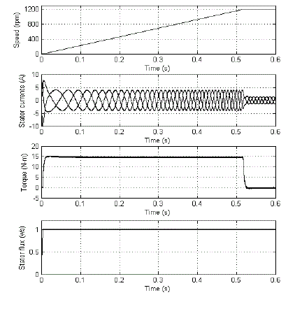
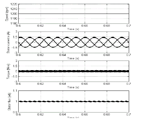
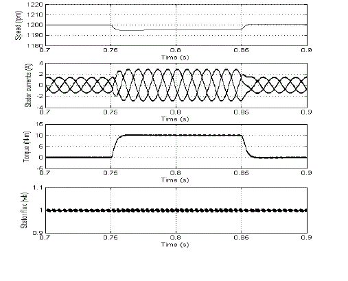
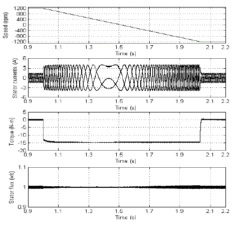
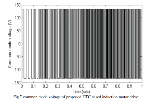
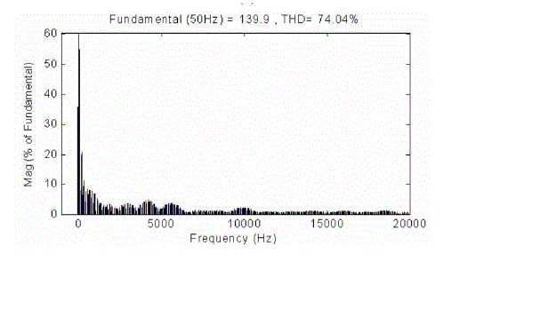
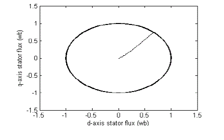
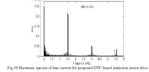
| To verify the proposed scheme, numerical simulation studies have been carried out by using Matlab/Simulink. For the simulation, the reference flux is taken as 1wb and starting torque is limited to 15 N-m. The induction motor used in this case study is a 1.5 kW, 1440 rpm, 4-pole, 3-phase induction motor having the following parameters: Rs = 7.83Ω, Rr = 7.55 Ω, Ls = 0.4751H, Lr = 0.4751H, Lm = 0.4535 H and J = 0.06 Kg.m2 . Fig .3 shows the transients during starting and Fig 4 shows the steady state plots of torque, current and stator flux at 1200 rpm. Moreover, it can be observed that, the proposed DTC gives reduced ripples in torque, current and stator flux during steady state when compared to the CDTC. Fig 5 shows the transient responses during the step change in load. The transients in speed, torque and currents during the speed reversals from +1200 rpm to 1200 rpm are shown in Fig 6. The Fig 7 and Fig 8 shows common mode emission of voltage and Harmonic distortion of common mode voltage for the proposed DTC, from which it can be observed that the common mode voltage is low when compared to the conventional DTC. The locus of the stator flux at 1200 rpm is shown in Fig 9, from which it can be observed that the locus is almost is a circle of constant radius. The wave form of the harmonic distortion of the line current is given in Fig 10 along with the total harmonic distortion (THD) value and it has been shown that the THD of proposed DTC is low when compared to the CDTC. |
VII. CONCLUSION
|
| In this paper, the dynamic behaviour of the induction motor under both transient and steady state conditions, an accurate mathematical model of the induction motor has been developed in the stationary reference frame. Thus, with the proposed method, the common mode emissions of direct torque controlled induction motor drive system can be decreased compared to CDTC with slight increase in torque, stator current and stator flux ripples. From the simulation results it can be concluded that with the proposed DTC algorithm the common mode voltages are reduced. |
Tables at a glance
|
 |
| Table 1 |
|
| |
Figures at a glance
|
 |
 |
 |
 |
 |
| Figure 1 |
Figure 2 |
Figure 3 |
Figure 4 |
Figure 5 |
 |
 |
 |
 |
 |
| Figure 6 |
Figure 7 |
Figure 8 |
Figure 9 |
Figure 10 |
|
| |
References
|
- B. K. Bose, "Modern Power Electronics and AC drives", Prentice-Hall, 2002.
- Werner Leonard, “Control of electrical drives” Springer-Verlag, Third Edition, 2003.
- Peter Vas, “Sensorless vector and direct torque control” Oxford university press, New York, 1998.
- Li Zhen, LongyaXu, “A Mutual MRAS Identification Scheme for Position Sensorless Field Orientation Control of InductionMachines”, IEEE IAS Annual Meeting, pg. 159 - 165. 1995
- F. Blaschke, "The principle of fiels-orientation as applied to the Transvector closed-loop control system for rotating-fieldmachines", in Siemens Reviev 34, 1972, pp.217-220.
- J.C. Trounce, S.D. Round, R.M. Duke. Comparison by Simulation of Three-Level Induction Motor Torque Control Schemesfor Electric Vehicle Applications. Proc. Of International Power Engineering Conference Singapore, May 2001, vol. 1, pp.294-299.
- NikRumziNikIdris and Abdul Halim Mohamed Yatim, “Direct torque control of induction machines with constant switching frequency and reduced torque ripple” IEEE Trans. Ind Electron., vol. 51, no. 4, Aug 2004, pp. 758-767.
- Marian P. Kazmierkowski and Andrzej B. Kasprowicz, “Improved direct torque and flux vector control of PWM inverter-fed induction motor drives” IEEE Trans. Ind. Electron., vol. 42, no. 4, Aug 1995, pp. 344-350.
- JunfengXu, JainpingXu, YingleiXu and Fengyan Wang, “Direct torque control of induction machines using discrete spacevector modulation applied to traction” IEEE Proc., 2003, pp. 1200-1202.
- Ananthalakshmi.V, V. C. Veera Reddy, M. Surya Kalavathi “Space Vector Based Hybrid PWM Algorithm for Direct Torque Controlled Induction Motor Drives for Reduced Common Mode Voltage” Journal of Electrical Engineering : Volume 12 /2012 - Edition : 3.
|