This paper presents a new component within the flexible ac-transmission system (FACTS) family, called multi connected distributed power-flow controller (MC-DPFC) capable of simultaneous compensation for voltage and current in multibus/multifeeder systems. In this configuration, one shunt voltage-source converter (shunt VSC) and two or more series VSCs exist. The system can be applied to adjacent feeders to compensate for supply-voltage and load current imperfections on the main feeder and full compensation of supply voltage Imperfections on the other feeders. The DPFC can be considered as a UPFC with an eliminated common dc link. The active power exchange between the shunt and series converters, which is through the common dc link in the UPFC, is now through the transmission lines at the third-harmonic frequency. The DPFC employs the distributed FACTS (D-FACTS) concept, which is to use multiple small-size single-phase converters instead of the one large-size three-phase series converter in the UPFC. In this proposed system we connected DPFC for multiple bus bars instead of using two custom power devices (CUPS). The large number of series converters provides redundancy, thereby increasing the system reliability. As the D-FACTS converters are single-phase and floating with respect to the ground, there is no high-voltage isolation required between the phases. Accordingly, the cost of the DPFC system is lower than the UPFC. The DPFC has the same control capability as the UPFC, which comprises the adjustment of the line impedance, the transmission angle, and the bus voltage. The principle and analysis of the DPFC are presented.
Keywords |
| Power Quality, Facts Technology, Distributed Power Flow Controller (DPFC), Total Harmonic Distortion. |
INTRODUCTION |
| With increasing applications of nonlinear and electronically switched devices in distribution systems and industries, power-quality
(PQ) problems, such as harmonics, flicker, and imbalance have become serious concerns. In addition, lightning strikes on
transmission lines, switching of capacitor banks, and various network faults can also cause PQ problems, such as transients, voltage
sag/swell, and interruption. On the other hand, an increase of sensitive loads involving digital electronics and complex process
controllers requires a pure sinusoidal supply voltage for proper load operation. In order to meet PQ standard limits, it may be
necessary to include some sort of compensation. Modern solutions can be found in the form of active rectification or active
filtering. A shunt active power filter is suitable for the suppression of negative load influence on the supply network, but if there are
supply voltage imperfections, a series active power filter may be needed to provide full compensation. And also we have
compensation techniques such as tapping transformers, shunt condensers etc. |
| In recent years, solutions based on flexible ac transmission systems (FACTS) have appeared. The application of FACTS concepts
in distribution systems has resulted in a new generation of compensating devices. Currently, the distributed power-flow controller
(DPFC) shown in Fig. is the most powerful FACTS device, which can simultaneously control all the parameters of the system: sag,
swell, flickers and bus bar voltages. It is similar to Unified Power Flow Controller (UPFC). The UPFC is the combination of a static
synchronous compensator (STATCOM) and a static synchronous series compensator (SSSC), which are coupled via a common dc
link, to allow bidirectional flow of active power between the series output terminals of the SSSC and the shunt output terminals of
the STATCOM. The unified power quality conditioner (UPQC) compensator seems to be a particularly promising power
conditioner device. This apparatus is constituted of a series and a shunt unit, with a common dc section through which power can be exchanged. Its function is to improve the quality levels of the current absorbed at the mains and the load supply voltage. The
installation investments are also quite high relative to the power quality level obtained. A solution that has similar performances and
advantages, but also makes cost reduction possible, is the proposed MC-DPFC. |
| Advance of UPFC is DPFC. The DPFC is able to control all system parameters. The DPFC eliminates the common dc link between
the shunt and series converters. The active power exchange between the shunt and the series converter is through the transmission
line at the third-harmonic frequency. |
| Comparing with the UPFC, the DPFC have two major advantages: 1) low cost because of the low-voltage isolation and the
low component rating of the series converter and 2) high reliability because of the redundancy of the series converters. In this
paper we modified DPFC as for multi feeders which are in adjacent. So the main advantage is we can use DPFC for two or
more power generations without increasing economical and with max pure sinusoidal output. |
DPFC PRINCIPLE |
| The DPFC consists of one shunt and several series-connected converters. The shunt converter is similar as a STATCOM,
while the series converter employs the D-FACTS concept, which is to use multiple single-phase converters instead of one
large rated converter. Each converter within the DPFC is independent and has its own dc capacitor to provide the required dc
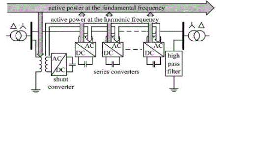
voltage. The configuration of the DPFC is shown in Fig 2 , besides the key components, namely the shunt and series
converters, the DPFC also requires a high-pass filter that is shunt connected at the other side of the transmission line, and two
Y–Δ transformers at each side of the line. The unique control capability of the UPFC is given by the back-to-back connection
between the shunt and series converters, which allows the active power to exchange freely. To ensure that the DPFC have the
same control capability as the UPFC, a method that allows the exchange of active power between converters with eliminated
dc link is the prerequisite. Within the DPFC, there is a common connection between the ac terminals of the shunt and the
series converters, which is the transmission line. Therefore, it is possible to exchange the active power through the ac
terminals of the converters. The method is based on the power theory of non sinusoidal components. |
| According to the Fourier analysis, a non sinusoidal voltage and current can be expressed by the sum of sinusoidal functions in
different frequencies with different amplitudes. The active power resulting from this non sinusoidal voltage and current is
defined as the mean value of the product of voltage and current. -Since the integrals of all the cross product of terms with
different frequencies are zero, the active power can be expressed by |
 |
| By applying this method to the DPFC, the shunt converter can absorb active power from the grid at the fundamental
frequency and inject the current back into the grid at a harmonic frequency. This harmonic current will flow through the
transmission line. According to the amount of required active power at the fundamental frequency, the DPFC series
converters generate a voltage at the harmonic frequency, thereby absorbing the active power from harmonic components.
Assuming a lossless converter, the active power generated at fundamental frequency is equal to the power absorbed from the
harmonic frequency. For a better understanding, Fig. 3 indicates how the active power exchanges between the shunt and the
series converters in the DPFC system. The high-pass filter within the DPFC blocks the fundament frequency components
and allows the harmonic components to pass, thereby providing a return path for the harmonic components. The shunt and
series converters, the high-pass filter, and the ground form the closed loop for the harmonic current. Due to the unique
characters of third-harmonic frequency components, the third harmonic is selected to exchange the active power in the DPFC.
In a three-phase system, the third harmonic in each phase is identical, which is referred to as “zero-sequence.” The zerosequence
harmonic can be naturally blocked by Y–Δ transformers, which are widely used in power system to change voltage
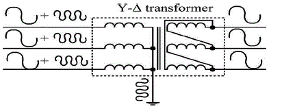
level. Therefore, there is no extra filter required to prevent the harmonic leakage to the rest of the network. In addition, by
using the third harmonic, the costly high-pass filter, as shown in Fig. 3, can be replaced by a cable that is connected between
the neutral point of the Y–Δ transformer on the right side in Fig. 3 and the ground. Because the Δ winding appears open
circuit to the third-harmonic current, all harmonic current will flow through the Y-winding and concentrate to the grounding
cable, as shown in Fig. 4. Therefore, the large-size high-pass filter is eliminated. |
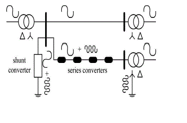
| Another advantage of using third harmonic to exchange active power is that the way of grounding of Y–Δ transformers can be
used to route the harmonic current in a meshed network. If the branch requires the harmonic current to flow through, the
neutral point of the Y–Δ transformer at the other side in that branch will be grounded and vice versa. Fig. 6 demonstrates a
simple example of routing the harmonic current by using a grounding Y–Δ transformer. Because the transformer of the line
without the series converter is floating, it is open circuit for third-harmonic components. Therefore, no third-harmonic current
will flow through this line. |
| Theoretically, the third-, sixth-, and ninth-harmonic frequencies are all zero-sequence, and all can be used to exchange active
power in the DPFC. As it is well known, the capacity of a transmission line to deliver power depends on its impedance. Since
the transmission-line impedance is inductive and proportional to the frequency, high-transmission frequencies will cause high
impedance. Consequently, the zero-sequence harmonic with the lowest frequency—third harmonic is selected. |
PROPOSED MC-DPFC SYSTEM |
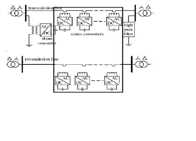
| Here we used Multi Connected Distributed Power Flow Controller (MC-DPFC) which is used for more than one bus bars
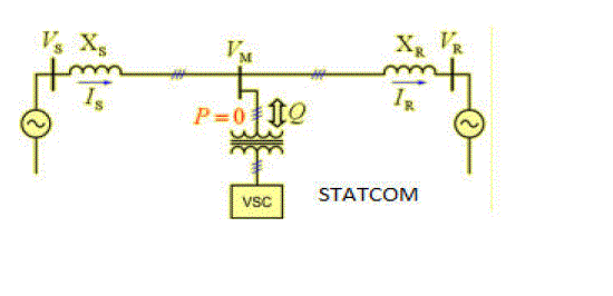
simultaneously. The schematic diagram of MC-DPFC is as shown in Fig 6. |
| Here for system one it acts as shunt-series converter like dpfc. For system two it acts as only acts as single phase series
converter i.e. DVR. The main advantage of this system is there is no need to use two FACT devices for two bus bars. Within
low cost we can gain power quality. STATCOM is a device connected in derivation, basically composed of a coupling
transformer, that serves of link between the electrical power system (EPS) and the voltage synchronous controller (VSC), that
generates the voltage wave comparing it to the one of the electric system to realize the exchange of reactive power. The
control system of the STATCOM adjusts at each moment the inverse voltage so that the current injected In the network is in
quadrature to the network voltage, in these conditions P=0 and Q=0. |
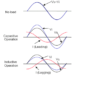
| The angle between the Vs and Vi in the system is d. When the STATCOM operates with d=0 we can see how the active
power send to the system device becomes zero while the reactive power will mainly depend on the voltage module. This
operation condition means that the current that goes through the transformer must have a +/-90º phase difference to Vs. In
other words, if Vi is bigger than Vs, the reactive will be send to the STATCOM of the system (capacitive operation),
originating a current flow in this direction. In the contrary case, the reactive will be absorbed from the system through the
STATCOM (inductive operation) and the current will flow in the opposite direction. Finally if the modules of Vs and Vi are
equal, there won´t be nor current nor reactive flow in the system. Thus, we can say that in a stationary state Q only depends
on the module difference between Vs and Vi voltages. The amount of the reactive power is proportional to the voltage
difference between Vs and Vi. |
| There can be a little active power exchange between the STATCOM and the EPS. The exchange between the inverter and the
AC system can be controlled adjusting the output voltage angle from the inverter to the voltage angle of the AC system. This
means that the inverter can not provide active power to the AC system form the DC accumulated energy if the output voltage
of the inverter goes before the voltage of the AC system. On the other hand, the inverter can absorb the active power of the
AC system if its voltage is delayed in respect to the AC system voltage. |
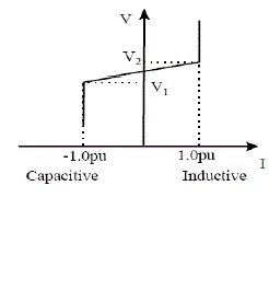
| The STATCOM smoothly and continuously controls voltage from V1 to V2. However, if the system voltage exceeds a lowvoltage
(V1) or high-voltage limit (V2), the STATCOM acts as a constant current source by controlling the converter voltage
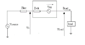
(Vi) appropriately. DVR is series connected FACT device. The main function of a DVR is the protection of sensitive loads
from voltage sags/swells coming from the network. The DVR is located on approach of sensitive loads. If a fault occurs on
other lines, DVR inserts series voltage VDVR and compensates load voltage to pre fault value. The momentary amplitudes of
the three injected phase voltages are controlled such as to eliminate any detrimental effects of a bus fault to the load voltage
VL. This means that any differential voltages caused by transient disturbances in the ac feeder will be compensated by an
equivalent voltage generated by the converter and injected on the medium voltage level through the booster transformer. |
| The DVR works independently of the type of fault or any event that happens in the system, provided that the whole system
remains connected to the supply grid, i.e. the line breaker does not trip. For most practical cases, a more economical design
can be achieved by only compensating the positive and negative sequence components of the voltage disturbance seen at the
input of the DVR. This option is Reasonable because for a typical distribution bus configuration, the zero sequence part of a
disturbance will not pass through the step down transformer because of infinite impedance for this component. The DVR has
two modes of operation which are: standby mode and boost mode. In standby mode (VDVR=0), the booster transformer’s low
voltage winding is shorted through the converter. No switching of semiconductors occurs in this mode of operation, because
the individual converter legs are triggered such as to establish a short-circuit path for the transformer connection. Therefore,
only the comparatively low conduction losses of the semiconductors in this current loop contribute to the losses. The DVR
will be most of the time in this mode. In boost mode (VDVR>0), the DVR is injecting a compensation voltage through the
booster transformer due to a detection of a supply voltage disturbance. |
| When the source voltage is drop or increase, the DVR injects a series voltage Vinj through the injection transformer so that
the desired load voltage magnitude VL can be maintained |
DPFC CONTROL |
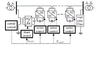
| To control the multiple converters, DPFC consists of three types of controllers; they are central controller, shunt control, and
series control, as shown in Fig 11 |
| The shunt and series control are local controllers and are responsible for maintaining their own converters’ parameters. The
central control takes account of the DPFC functions at the power-system level. The function of each controller is listed next.\ |
| A. Central Control |
| The central control generates the reference signals for both the shunt and series converters of the DPFC. It is focused on the
DPFC tasks at the power-system level, such as power-flow control, low-frequency power oscillation damping, and balancing
of asymmetrical components. According to the system requirement, the central control gives corresponding voltage-reference
signals for the series converters and reactive current signal for the shunt converter. All the reference signals generated by the
central control are at the fundamental frequency. |
| B. Shunt Control |
| The shunt connected STATCOM with battery energy storage is connected with the interface of the induction generator and
non-linear load at the PCC in the grid system. The STATCOM compensator output is varied according to the controlled
strategy, so as to maintain the power quality norms in the grid system. The current control strategy is included in the control
scheme that defines the functional operation of the STATCOM compensator in the power system. A single STATCOM using
insulated gate bipolar transistor is proposed to have a reactive power support, to the induction generator and to the nonlinear
load in the grid system. |
| C. Series Control |
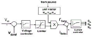
| Each series converter has its own series control. The controllers used to maintain the capacitor dc voltage of its own converter
by using the third-harmonic frequency components and to generate series voltage at the fundamental frequency that is
prescribed by the central control. The third-harmonic frequency control is the major control loop with the DPFC series
converter control. The principle of the vector control is used here for the dc-voltage control. The third-harmonic current
through the line is selected as the rotation reference frame for the single-phase park transformation, because it is easy to be
captured by the phase-locked loop (PLL) in the series converter. As the line current contains two frequency components, a
third high-pass filter is needed to reduce the fundamental current. The d-component of the third harmonic voltage is the
parameter that is used to control the dc voltage, and its reference signal is generated by the dc-voltage control loop. To
minimize the reactive power that is caused by the third harmonic, the series converter is controlled as a resistance at the thirdharmonic
frequency. The q-component of the third-harmonic voltage is kept zero during the operation. As the series converter
is single phase, there will be voltage ripple at the dc side of each converter. The frequency of the ripple depends on the
frequency of the current that flows through the converter. As the current contains the fundamental and third harmonic
frequency component, the dc-capacitor voltage will contain 100-, 200-, and 300-Hz frequency component there are two
possible ways to reduce this ripple. One is to increase the turn ratio of the single-phase transformer of the series converter to
reduce the magnitude of the current that flows into the converter. The other way is to use the dc capacitor with a larger
capacitance. |
| A simulation setup has been built to verify the principle and control of the DPFC. One shunt converter and six single phase
series converters are built and tested in a scaled network, as shown in Fig13. Two isolated buses with phase difference are
connected by the line. Within the experimental setup, the shunt converter is a single-phase inverter that is connected between
the neutral point of the Y–Δ transformer and the ground. The inverter is powered by a constant dc-voltage source. |
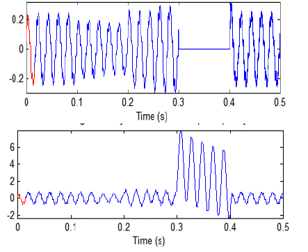
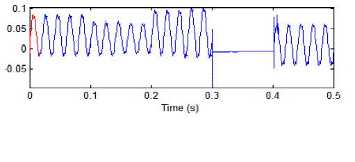
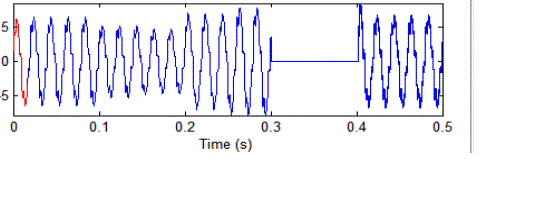
| Fig 13; shows the voltages and currents at bus-Bar 1. Here at the time period from 0.1 to 0.2 we have voltage sag and from
0.2 to 0.3 voltage swell and from 0.3to 0.4 fault currents. |
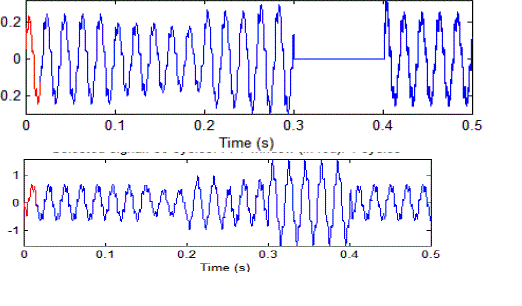
| Fig 14: shows the voltages and currents at bus-Bar 2. Here at the time period from 0.1 to 0.2 we have voltage sag and from
0.2 to 0.3 voltage swell and from 0.3to 0.4 fault currents. |
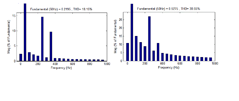
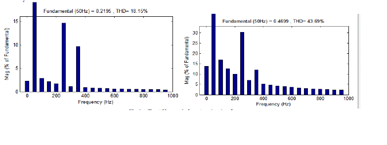
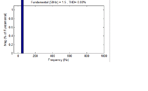
| Fig 15: shows the total harmonic levels at busbar1 voltage and currents respectively. |
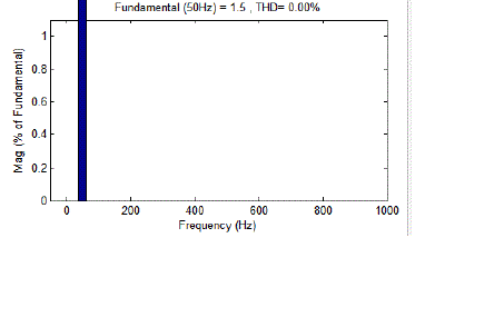
| Fig 16: shows the total harmonic levels at busbar1 voltage and currents respectively. |
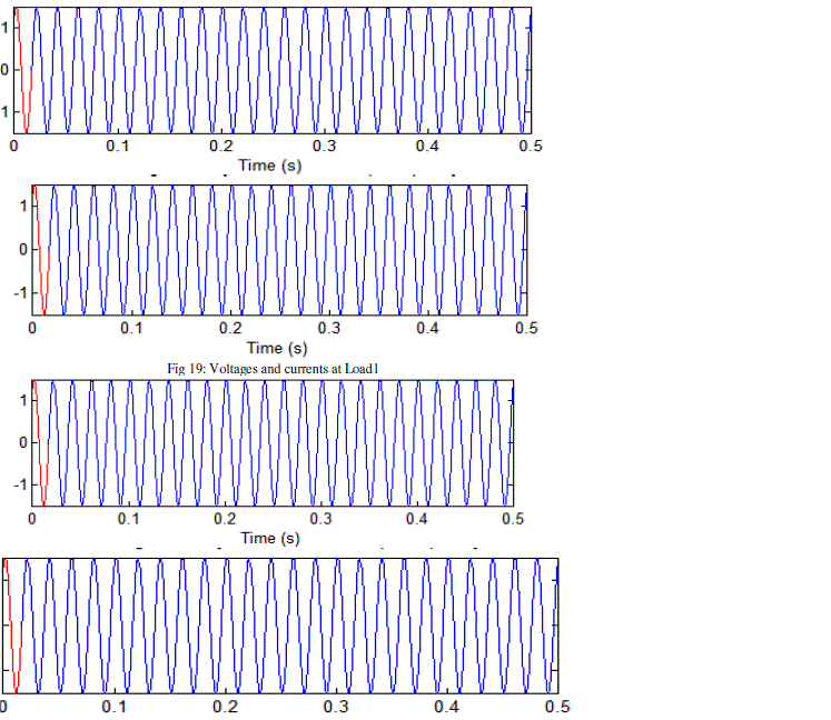
| To mitigate the high voltages, sag, fault currents shown in fig 17 we injects current at bus bar1 by STATCOM principle as
shown in fig 19. |
| Fig 18 and Fig 20 Shows the output voltages and currents at load 1 and load 2. |
CONCLUSION |
| This paper has presented a new concept called MC-DPFC. The MC-DPFC emerges from the UPFC and inherits the control
capability of the UPFC, which is the simultaneous adjustment of the line impedance, the transmission angle, and the busvoltage
magnitude. The common dc link between the shunt and series converters, which is used for exchanging active power
in the UPFC, is eliminated. This power is now transmitted through the transmission line at the third-harmonic frequency. The
series converter of the DPFC employs the D-FACTS concept, which uses multiple small single-phase converters instead of
one large-size converter. The reliability of the DPFC is greatly increased because of the redundancy of the series converters.
The total cost of the DPFC is also much lower than the UPFC, because no high-voltage isolation is required at the seriesconverter
part and the rating of the components of is low. The DPFC concept has been verified by an experimental setup. It is
proved that the shunt and series converters in the DPFC can exchange active power at the third-harmonic frequency, and the
series converters are able to inject controllable active and reactive power at the fundamental frequency. |
Figures at a glance |
 |
 |
 |
 |
 |
| Figure 1 |
Figure 2 |
Figure 3 |
Figure 4 |
Figure 5 |
 |
 |
 |
 |
| Figure 6 |
Figure 7 |
Figure 8 |
Figure 9 |
 |
 |
 |
 |
| Figure 10 |
Figure 11 |
Figure 12 |
Figure 13 |
 |
 |
 |
 |
| Figure 14 |
Figure 15 |
Figure 16 |
Figure 17 |
 |
 |
 |
 |
| Figure 18 |
Figure 19 |
Figure 20 |
Figure 21 |
|
| |
References |
- Y.-H. Song and A. Johns, Flexible ac Transmission Systems (FACTS) (IEEE Power and Energy Series), vol. 30. London, U.K.: Institution of Electrical Engineers, 1999.
- N. G. Hingorani and L. Gyugyi, Understanding FACTS : Concepts and Technology of Flexible AC Transmission Systems. New York: IEEE Press, 2000.
- G.Satyanarayana., K.N.V Prasad, G.Ranjith Kumar, K. Lakshmi Ganesh, "Improvement of power quality by using hybrid fuzzy controlled based IPQC at various load conditions," Energy Efficient Technologies for Sustainability (ICEETS), 2013 International Conference on , vol., no., pp.1243,1250, 10-12 April 2013.
- A.-A. Edris, âÃâ¬ÃÅProposed terms and definitions for flexible ac transmission system (facts),âÃâ¬Ã IEEE Trans. Power Del., vol. 12, no. 4, pp. 1848âÃâ¬Ãâ1853, Oct. 1997.
- K.N.V. Prasad, G.Ranjith Kumar, Y.S. Anil Kumar, G. Satyanarayana, "Realization of cascaded H-bridge 5-Level multilevel inverter as Dynamic Voltage Restorer," Computer Communication and Informatics (ICCCI), 2013 International Conference on , vol., no., pp.1,6, 4-6 Jan. 2013.
- M. D. Deepak, E. B. William, S. S. Robert, K. Bill, W. G. Randal, T. B. Dale, R. I. Michael, and S. G. Ian, âÃâ¬ÃÅA distributed static series compensator system for realizing active power flow control on existing power lines,âÃâ¬Ã IEEE Trans. Power Del., vol. 22, no. 1, pp. 642âÃâ¬Ãâ649, Jan.2007.
- K.N.V Prasad, G.Ranjith Kumar, T. VamseeKiran, G.Satyanarayana., "Comparison of different topologies of cascaded H-Bridge multilevel inverter," Computer Communication and Informatics (ICCCI), 2013 International Conference on , vol., no., pp.1,6, 4-6 Jan. 2013
- Y. Zhihui, S.W. H. de Haan, and B. Ferreira, âÃâ¬ÃÅUtilizing distributed power flow controller (dpfc) for power oscillation damping,âÃâ¬Ã in Proc. IEEE Power Energy Soc. Gen. Meet. (PES), 2009, pp. 1âÃâ¬Ãâ5.
- G. SatyaNarayana, Ch. Narendra Kumar, Ch. Rambabu âÃâ¬ÃÅ A Comparative Analysis of PI Controller and Fuzzy Logic Controller for Hybrid Active Power Filter Using Dual Instantaneous Power TheoryâÃâ¬Ã International Journal of Engineering Research & Development, Vol-4, Issue-6, p.p. 29-39, Oct, 2012.
- Y. Sozer and D. A. Torrey, âÃâ¬ÃÅModeling and control of utility interactive inverters,âÃâ¬Ã IEEE Trans. Power Electron., vol. 24, no. 11, pp. 2475âÃâ¬Ãâ2483, Nov. 2009.
- K.N.V Prasad, G.Ranjith Kumar, T. VamseeKiran, G.Satyanarayana., "Comparison of different topologies of cascaded H-Bridge multilevel inverter," Computer Communication and Informatics (ICCCI), 2013 International Conference on , vol., no., pp.1,6, 4-6 Jan. 2013.
|