Keywords
|
| Cascaded H-bridge, multilevel inverter, Sinusoidal pulse width modulation, Total harmonic distortion. |
INTRODUCTION
|
| Multilevel inverters include an array of power semiconductors and dc voltage sources, the output of which generate voltage with stepped waveform [1] in comparison with a two-level voltage-source inverter (VSI). The multilevel voltage source inverter enables to synthesize output voltages with reduced harmonic distortion and lower electromagnetic interference [2].By increasing the number of levels in multilevel inverter output voltage have more steps in generating a staircase waveform, which has a reduced harmonic distortion. However a larger number of levels increase the number of devices that must be controlled and control complexity [3]. As a result, the most attractive applications of this technology are in medium to high voltage ranges. A multilevel inverter not only achieves high power ratings, but also enables the use of renewable energy sources such as photovoltaic, wind and fuel cells which can be easily interfaced to a multilevel inverter system for a high power application. The advantages of multilevel inverters are their smaller output voltage step, which results in high voltage capability, lower harmonic components, lower switching losses, better electromagnetic compatibility and high power quality. Also it can operate at both fundamental switching frequency and high switching frequency PWM. The field applications include use in laminators, pumps, conveyors, compressors fans, blowers and mills. Subsequently, several multilevel inverter topologies have been developed. |
| Three different topologies have been proposed for multilevel inverters namely Neutral point clamped (NPC) multilevel inverter, flying capacitor (FC) multilevel inverter and cascaded H-bridge (CHB) multilevel inverter[4],[5]. The NPC multilevel inverter also called diode clamped can be consider the first generation of multilevel inverter introduced by Nabae et al.[6], which was a three level inverter. The three-level case of the NPC multilevel inverter has been widely applied in different industries. Unlike the NPC type, the FC multilevel inverter offers some redundant switching states that can be used to regulate capacitors voltage. However, the control scheme becomes complicated. Moreover, the number of capacitors increases by increasing the number of voltage levels. The CHB multilevel inverter use series connected H-bridge cells with isolated dc sources connected to each cell. The cascaded H-bridge multilevel inverter can be divided into two groups from view point of values of the DC voltage sources namely the symmetric and the asymmetric topology. In the symmetric topology, the values of all of the DC voltage sources are equal. This characteristic gives the topology good modularity. However, the number of switching devices rapidly increases with increase in the number of output voltage levels. If the values of the DC voltage sources selected are different, then these topologies are called asymmetric [7],[8].The CHB multilevel inverters have been industrially employed in several application fields such as pumps, fans, compressors ,etc. In addition, they have recently been proposed for other applications like photovoltaic power-conversion systems and wind power conversion. |
| This paper proposes a novel multilevel inverter topology using three series-connected sub multilevel inverters. The proposed topology uses a PV cell as one DC source and other two DC voltage sources connected in series. Several modulation techniques have been developed for multilevel inverters such as sinusoidal pulse width modulation (SPWM), selective harmonic elimination pulse width modulation (SHE-PWM), space vector modulation (SVM) [9], but due its simplicity, fast response and its suitability for multilevel inverters, SPWM is used in this paper to control the inverter switches. The proposed topology for multilevel inverter has seven levels associated with a nine number of power switches. In addition, many multilevel inverter applications focus on industrial medium-voltage motor drives, utility interface for renewable energy systems, flexible AC transmission system (FACTS) and traction drive systems. This characteristic gives this topology good modularity. |
CONVENTIONAL CASCADED MULTILEVEL INVERTER
|
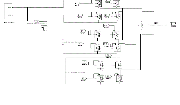
| Conventional cascaded multilevel inverters are one of the most important topologies in the family of multilevel and multiples inverters. The cascaded topology allows the use of several levels of DC voltages to synthesize a desired AC voltage. It requires least number of components when compared to diode-clamped and flying capacitors type multilevel inverters and no specially designed transformer is needed as compared to multi pulse inverter. A cascaded multilevel inverter consists of a number of H-bridge inverter units with separate DC source for each unit and it is connected in cascaded or series. Fig.1 shows a seven level inverter with three H-bridges connected in series. It requires 12 IGBT switches. Photo voltaic (PV) array is used as one source and another two sources are DC sources. The PV array can be used for producing DC voltage from the sun light directly in to electricity. In order to obtain the desired voltage from PV array the duty ratio of the switches is adjusted by controlling the gate pulses to the switches. |
| In this Inverter all the DC sources are of same voltage equal to vdc and therefore the number of voltage levels are represented by eqn .(1). |
 (1) (1) |
| where ‘n’ is the number of separate DC sources and nlevel is the number of output voltage levels. |
PROPOSED NOVEL SEVEN LEVEL INVERTER USING PV CELL
|
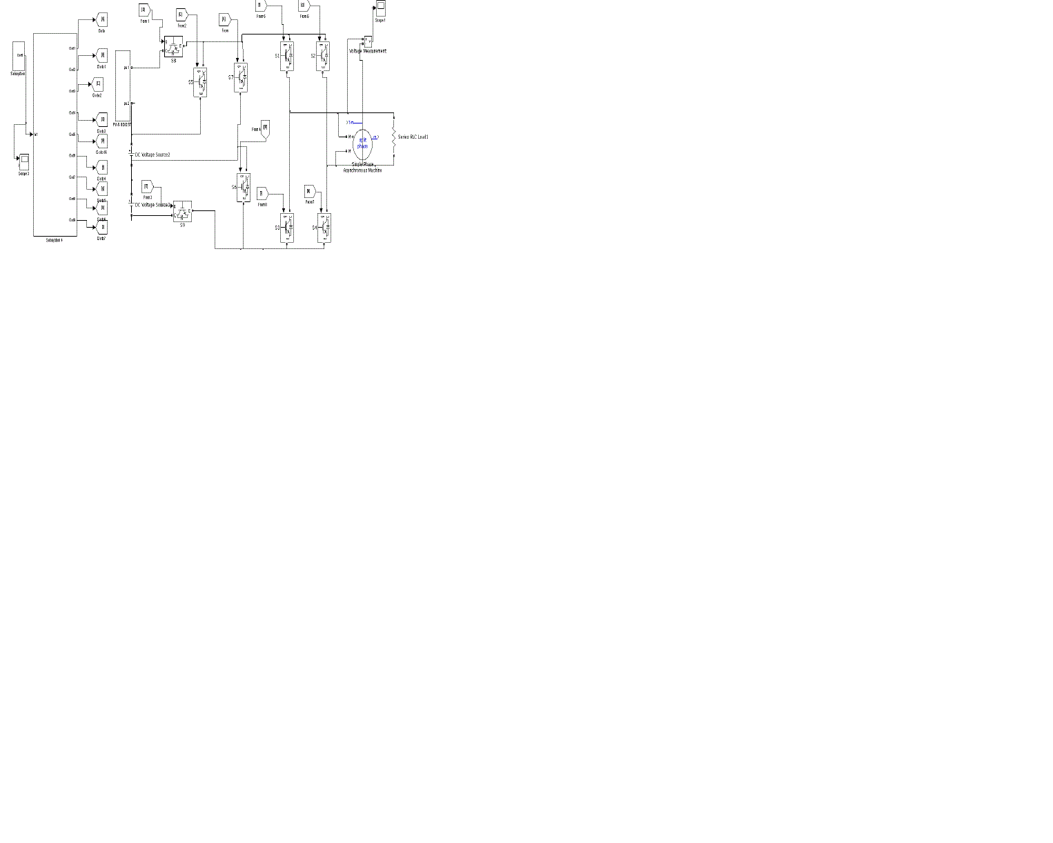
| The block diagram of the proposed novel cascaded seven level inverter using PV cell is shown in Figure. 2. It consists of three sources connected in series, one is PV cell and the other two are DC sources of voltage 500V each. The proposed inverter uses nine IGBTs controlled by gating pulses. SPWM technique is used to control the inverter switches. Proposed inverter is connected to single phase asynchronous motor to evaluate the performance of the inverter. By using this proposed inverter harmonic content on load side is reduced compared with a seven level cascaded inverter. The proposed seven level inverter produces seven level stepped voltage waveform through 1500V,1000V,750V,0V, -750V,-1000V,-1500V. |
| A) PV cell model |
| Photovoltaic (PV) generation is becoming increasingly important as a renewable source since it offers many advantages such as incurring no fuel costs, not being polluting, requiring little maintenance and emitting no noise among others. But still, these modules have relatively low conversion efficiency due to their nonlinear and temperature-dependent voltage-current and voltage power characteristics [10]. Power generating by PV generators and injecting into the grid is gaining more and more visibility in the area of PV applications. This is mainly because the world’s power demand is steadily increasing. Solar cells produce direct current electricity from light, which can be used to power equipment or to recharge a battery. The PV arrays can be used either for standalone applications or grid connected. The first practical application of photovoltaic was to power orbiting satellites and other spacecraft and pocket calculators, but today the majority of photovoltaic modules are used for grid connected power generation. Grid connected photovoltaic energy conversion systems are composed of a DC-DC converter and an inverter. The DC-DC converter is controlled to track the maximum power point of the photovoltaic array and the inverter is controlled to produce voltage in such a way that the grid current has low total harmonic distortion (THD) and it is in phase with the grid voltage. In order to find the maxima point of power in PV module GSS algorithm is used because of its fast response, robust performance, and guaranteed convergence. |
| 1)GSS algorithm |
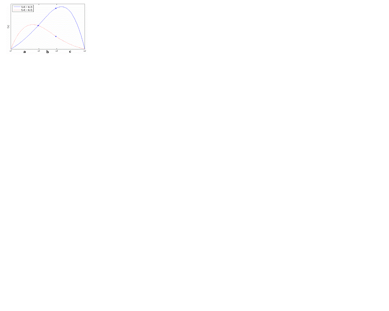
| Maximum power point tracking (MPPT) is typically a maxima-finding process. The procedures for finding a maximum with GSS technique is illustrated in Fig. 3. The goal is to find the maximum functional value of f(x) within the input interval (x1, x2). |
| The searching steps can be described as below |
| 1. Initially, the values of f(x1), f(x2) and f(x3) are already known. Because f(x3) is greater than f(x1) and f(x2), the maximum must lie inside the section of (x1, x2). |
| 2. The value of f(x4) at a new point x4 is being evaluated. |
| 3. If f(x4) > f(x3), the maximum point lies inside the section (x3, x2). The new point x4 is then inserted and x1 is discarded to create a new narrower search section (x3, x2) with still three known points x3, x4 and x2. |
| 4. If f(x4) < f(x3), the maximum point lies inside the section (x1, x4). The new point x4 is still inserted, but x2 is discarded to create another new narrower search section (x1, x4) with another set of three known points x1, x3 and x4. |
| . Repeat the steps through 2 to 4 for a certain number of times, or until the search section is small enough to ensure that the new inserted point can be considered the maximum point. Obviously, for each iterating step there are two possible search sections like (x3, x2) and (x1, x4) in Fig. 3. Only one of them will be selected to be the next search section. It is required that the two possible sections are equally wide. Otherwise, the convergence speed would be slowed down when the wider sections being taken more frequently in some worse cases. Therefore, the selection of the new point x4 must satisfy the requirement: width of (x1, x4) = width of (x3, x2), that is (a + b) = (b + c) in Fig. 3. As a result, it becomes possible that all the search sections of the iterations can have the same proportion of spacing between the three points such that the algorithm converges at a constant speed, i.e. |
 (2) (2) |
| Solve (2) to yield: |
 (3) (3) |
| where ø is the golden ratio. That is the reason why this search strategy is called GSS. |
| 2) Power conditioning unit |
| The power conditioning system provides regulated DC or AC power appropriate for the application. It is the major component of a PV system. The output of the PV is an unregulated DC voltage and it needs to be conditioned in order to be of practical use. The power conditioner section converts the raw power into useable power for different applications. The power conditioning unit also controls electricity’s frequency and maintains harmonics to an acceptable level. The purpose of conditioners is to adapt the electrical current from PV to suit the electrical needs of the application. The general configuration of the system will be the PV followed by a boost converter followed by an inverter. In general, the load for the boost stage is a filter and the inverter system. The boost converters for the PV will be operated in the voltage control mode. The boost converter is ideally suited for interfacing the inverter system with the PV system. |
| Based on the load conditions, the boost stage can be commanded to draw a specific amount of current from the PV with a ripple well defined by the frequency, size of the inductor, and duty ratio. Similarly, the inverter is used for the interfacing of the PV system to the load to provide the load with voltage/current with proper frequency phase and magnitude where the input for the inverter comes from the boost converter stage and the inverter (with the filter) becomes the load for the boost converter. The power conditioner is also used for the grid connection of the PV system. An electrical power-generating system that uses PV as the primary source of electricity generation and is intended to operate synchronously, and in parallel with the electric utility network is a grid-connected PV system |
| 3) DC-DC converter control loop |
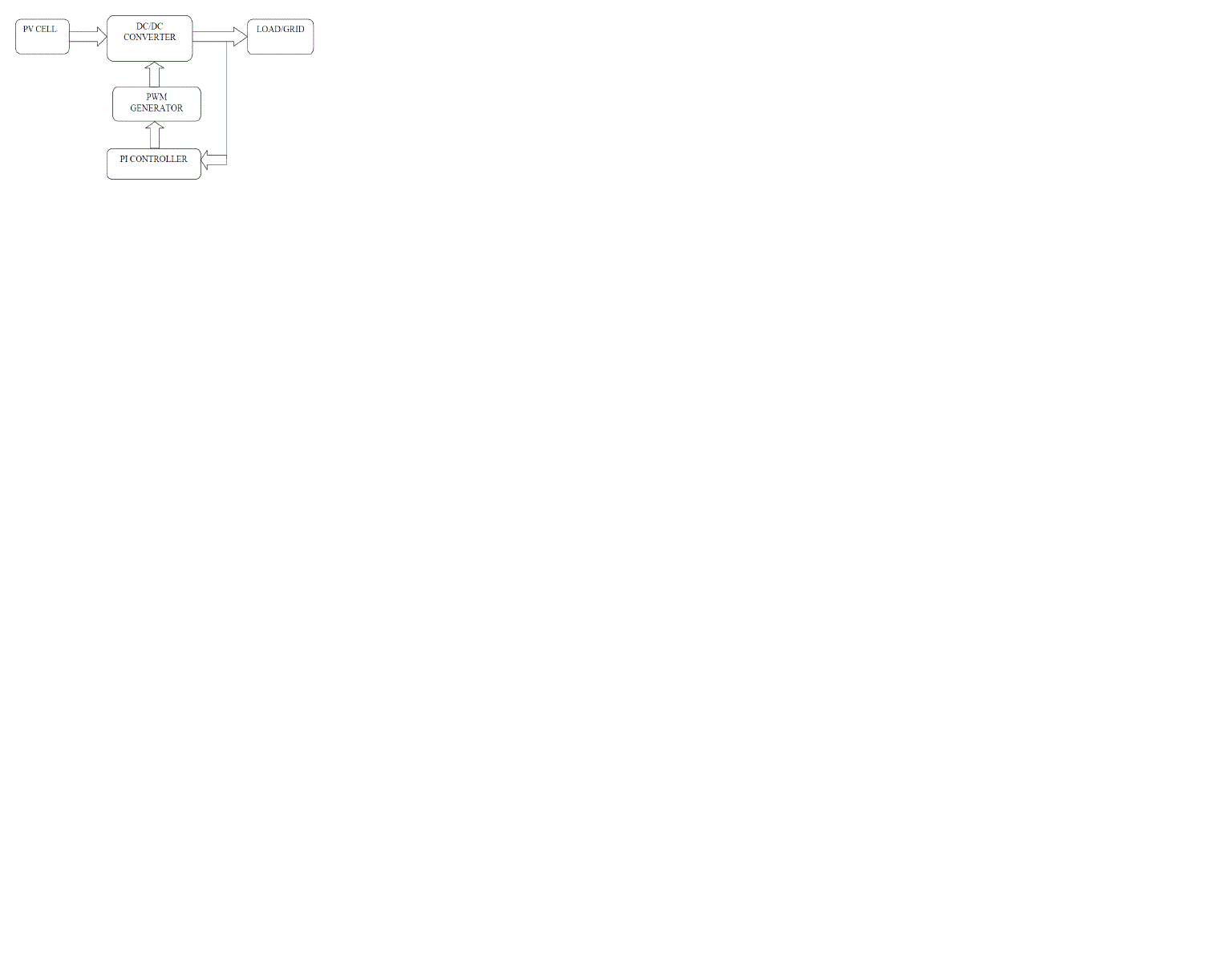
| The DC/DC converter control loop is shown in Figure. 5. The output voltage of PV system at the series of the stacks is uncontrolled DC voltage which fluctuates with temperature and irradiance. This raw voltage, which is unregulated and uncontrolled, is regulated to an average value with help of DC/DC converter. The controlled voltage thus obtained is fed to the DC/AC inverter after it is filtered. The power obtained from this inverter is added to the grid. This system can be used as a standalone after the DC/DC converter stage if DC power is needed or after the DC/AC stage if ac power is needed. |
| This unregulated voltage has to be adjusted to a constant average value (regulated dc voltage) by adjusting the duty ratio to the required value. The voltage is boosted depending upon the duty ratio. The duty ratio of the boost converter is adjusted with the help of a PI controller. The duty ratio is set at a particular value for the converter to provide desired average value of voltage at the output, and any fluctuation in the PV. The PI controller changes the duty ratio properly to get the desired average value. The duty ratio of the converter is changed by changing the pulses fed to the switch in the dc/dc converter circuit by the PWM generator. |
| 4) DC/AC inverter control loop |
| Inverters are devices that change the DC electricity produced by PV into AC electricity. Utility interactive inverters are used in systems connected to a utility power line. The inverters produce ac electricity in synchronization with the power line, and of a quality acceptable to the utility company once the control strategy is implemented. The inverter output voltage (i.e. load voltage) will be compared every time with the ref voltage. The change in the output voltage (due to change in the load) and grid voltage is given as inputs to the PI controller, and the output of the PI controller is given to the PWM generator and this generator will generate six pulses. These pulses will be given to the switches of the inverter which will change the duty ratio of the inverter. Due to this change in duty ratio the output voltage will be maintained constant during the loading conditions. |
| B) SPWM technique |
| Several different two-level multilevel carrier-based PWM techniques have been extended by previous authors as means for controlling the active devices in a multilevel converter. The most popular and easiest technique to implement uses several triangle carrier signals and one reference, or modulation signal per phase. There are three major carrier-based techniques used in a conventional inverter that can be applied in a multilevel inverter namely sinusoidal PWM (SPWM), third harmonic injection PWM (THPWM) and space vector PWM (SVPWM)[11]. SPWM is a very popular method in industrial applications. PWM technique is extensively used for eliminating harmful lower-order harmonics in inverter. In SPWM control, the inverter switches are turned ON and OFF several times during a half cycle and output voltage is controlled by varying the pulse width. It is the most widely accepted technique for modulation where in the reference signal is a sinusoidal signal with peak to peak amplitude Am, and frequency fm, and its zero centered in the middle of the carrier set as shown in Figure 6, and it is compared with (m-1) carrier signals, where ‘m’ is the number of levels with same frequency fc and same amplitude Ac. If the reference is greater than “s” carrier signal, then the active device corresponding to that carrier is switched off and of the reference is less than carrier signal then the switching device corresponding to that carrier is ON. SPWM techniques are characterized by constant amplitude pulses with different duty cycle for each period. The width of the pulses are modulated to obtain inverter output voltage control and to reduce its harmonic content [12]. In multilevel inverters, the amplitude modulation index “Ma” and the frequency ratio “Mf” are defined as |
 (4) (4) |
 (5) (5) |
RESULTS AND DISCUSSION
|
| The performance of proposed cascaded multilevel inverter is verified through simulation using MATLAB/SIMULINK and results are presented. |
| A) Results of conventional cascaded seven level inverter |
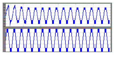
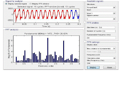
| The Fig. 7 shows the output voltage wave form of a conventional cascaded seven level inverter and Fig. 8 shows the harmonic spectra plot of output voltage. It is observed that the PWM technique used worked satisfactorily to produce seven levels in its output voltage and THD in source voltage is 26.42%. From the FFT analysis it can be inferred that when the number of levels is increased, the harmonic content and total harmonic distortion are reduced. |
| B) Results of Proposed Seven level multilevel inverter |
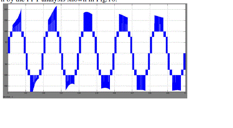
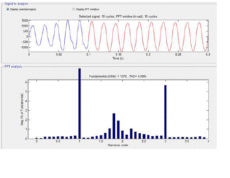
| The output voltage waveform of the proposed novel nine switch inverter is shown in Fig. 9 in which there are seven levels leading to lesser harmonics. This implies that the proposed SPWM worked well to produce required switching signals for the switches of inverter. The THD in the output voltage is reduced from 26.425 to 6.99% with the proposed nine switch inverter as shown by the FFT analysis shown in Fig.10. |
CONCLUSION
|
| In this project a conventional seven level cascaded H-bridge multilevel inverter is simulated using the MATLAB/SIMULINK with PV cell as one DC source and its performance in reducing THD is analyzed. Then the proposed seven level multilevel inverter with PV cell as one DC source is simulated using the MATLAB and the results are analyzed. By using this multilevel inverter harmonic content is reduced when compared to that of a conventional cascaded seven level inverter. It is observed that the output voltage of proposed seven level inverter is close to sinusoidal wave form when compared with conventional multilevel inverter. It can also observe that the quality of voltage wave form increases with increase in voltage levels. Also the SPWM technique controlled the inverter to produce seven levels in the output waveform. The main advantage of this novel topology is that the number of switching devices required is reduced by 33% leading to less cost, less losses and easy control in addition to fewer harmonic. |
Figures at a glance
|
 |
 |
 |
 |
 |
| Figure 1 |
Figure 2 |
Figure 3 |
Figure 4 |
Figure 5 |
 |
 |
 |
 |
 |
| Figure 6 |
Figure 7 |
Figure 8 |
Figure 9 |
Figure 10 |
|
| |
References
|
- J.Rodriguez, J.S. Lai, and F.Z peng, “Multilevel inverter: A survey of topologies, controls, and applications,” IEEE Trans. Ind. Electron., vol. 49, no. 4, pp. 724-738, Aug. 2002.
- J. H. Kim, S. K. Sul, and P. N. Enjeti, “A carrier-based PWM method with optimal switching sequence for a multilevel four-leg voltage-source Inverter,”IEEE Trans. Ind. Appl., vol.44, no.4,pp.1239-1248,Jul./Aug.2008.
- O. Lopez, J. Alvarez, J. Doval-Gandoy, F. D. Freijedo, A.Nogueiras, A. Lago, and C. M. Penalver, “Comparison of the FPGA implementation of two Multilevel space vector PWM algorithms,” IEEE Trans. Ind.Electron., vol. 55, no.4. 1537-1547, Apr.2008.
- A. A. Boora, A.Nami, F. Zare, A. Ghosh, and F. Blaabjerg, “Voltage-sharing converter to supply single-phase asymmetrical four- level diodeclamped Inverter with high power factor loads,” IEEE Trans. Power Electron., vol. 25, no. 10, pp.2507-2520, Oct. 2010.
- J. Rodriguez, S. Bernet, P.Steiemer, and I. Lizama, “A survey on neutral point clamped inverter,” IEEE Trans. Ind. Electron., vol.57, no. 7.pp. 2219- 223,Jul. 2010.
- A. Nabae, I. Takahashi, and H. Akagi, “A new neutral- point-clamped PWM inverter,” IEEE Trans. Ind. Appl., vol.IA-17, no.5, pp. 518- 523, sep./Oct. 1981.
- M.Manjrekar and T.A.Lipo,“A hybrid multilevel inverter topology for drive application,” in proc.Appl.PowerElectronic.Conf.,vol.2, pp.523-529,1998.
- A.Rufer, M. Veenstra, and A. Gopakumar, “Asymmetric multilevel converter for high resolution voltage phasor generation,” in Proc.Eur.Conf.Powerelectron.Appl., Lausanne,Switzerland, pp. 1-10,1999
- J. I. Leon, S. Kouro, S. Vazquez, R. Portillo, L. G. Franquelo, J. M.Carrasco, and J. Rodriguez,“Multidiamensional Modulation technique for cascaded Multilevel converters,” IEEE Trans. Ind.Electron., vol.58, no.2,pp. 412-420,Feb. 2011.
- N. Shanmugavadivu and T. Annamalai, “Single Phase Seven Level Stand Alone Inverter for Photovoltaic System,” Bonfring International Journal of Power Systems and Integrated Circuits, Vol. 2, Special Issue 1, Part 1,pp.49-53, February 2012.
- B.P. McGrath and Holmes, “Multicarrier PWM Strategies for Multilevel Inverter,” IEEE Transactions on Ind. Electronics., vol.49, no.4, pp.858-867, Aug.2002
- RoozbehNaderi, and AbdolrezaRahmati, “Phase Shifted Carrier PWM Technique for General Cascaded Inverters,” IEEE Transactions on Power Electronics, Vol.23, No.3, pp.1257-1269, May 2008
|