Keywords
|
| Particle Swarm Optimization, Continuation Power Flow, Maximum Loadability, Load Margin |
INTRODUCTION
|
| Voltage stability is an important aspect as power system is becoming heavily loaded or stressed day-by-day due to increase in power demand [1]. The stress on the system can be reduced by the expansion. However, the expansion of the system is limited due to the constraints imposed by environment and economy. Restructuring of the electrical power system has brought the voltage stability to the main focus. Voltage stability is concerned with the ability of a power system to maintain acceptable voltages at all buses in the system under normal conditions and after being subjected to a disturbance [2]. There are many reasons for voltage instability. One of them is increase in load demand. Voltage stability is due to the failure of system to meet needed reactive demand. Voltage instability may lead to voltage collapse. Many voltage collapse incidents have been reported [3]. Thus it is a fundamental concern in Planning and Operation of Power System. Margin analysis is one of the methods to find the voltage stability of the system. Continuation Power Flow is an extensively used method to find Maximum Loadability which uses continuation parameterization technique, corrector and predictor steps to draw a P-V curve for a particular bus in the system [4, 5]. It has been used to assess voltage security of the system [6]. It overcomes the problem of divergence near the critical point (Maximum Loadability, corresponding voltage) by using parameterization technique, which the conventional power flow methods suffer. The critical point is then used to find the Load Margin. Load Margin is the difference between actual operating point and Maximum Loadability point. |
| Many authors have used Evolutionary Computation Techniques to find Maximum Loadability Limit. Acharjee developed real coded security constraint Genetic Algorithm for Maximum Loadability Limit Problem and compared it with Particle Swarm Optimization [7]. Gnanambal and Babulal determined Maximum Loadability Limit using Hybridization of Particle Swarm Optimization and Differential Evolution to incorporate best qualities of both methods, namely quick convergence and superior performance in global optimization respectively [8]. El-Dib et al determined Maximum Loadability Limit using Hybrid Particle Swarm Optimization and compared it with Continuation Power Flow [9]. |
| Particle Swarm Optimization is an Evolutionary Computation Technique [10]. It is used to solve non-linear optimization problems. It overcomes problem of slow convergence and curse of dimensionality which the analytic methods suffer. It is a heuristics-based swarm intelligence method [11]. It has been used in various applications, reactive power and voltage control, power system reliability and security, power system identification and control, optimal power flow, economic dispatch scheduling, state estimation, load forecasting, control and others [11, 12]. In this paper, the proposed method searches for critical point without drawing P-V curve. Particle Swarm Optimization is used to optimize the formulated problem and the results are compared with Continuation Power Flow. |
CONTINUATION POWER FLOW
|
| Predictor, corrector, step length control, parameterization strategy are the characteristics of Continuation Power Flow. It is used to solve system of non linear equations. It can find solution near the critical point easily. For this, it uses local parameterization continuation technique [4, 5]. |
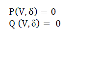
| Consider power flow equations (1) at load bus 2 in two bus system in Fig. 1. |
 (1) (1) |
| These equations (1) are added with a load parameter, λ. Thus equations (1) are modified to equations (2). |
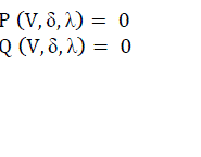 (2) (2) |
| where load change scenarios are incorporated in P and Q as in equations (3). |
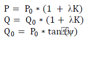 (3) (3) |
| where |
| P0 = original real power of load |
| Q0 = original reactive power of load |
| K = rate of change of load |
| Ψ = power factor angle of load |
| Original Jacobian matrix for this system is given by (4). |
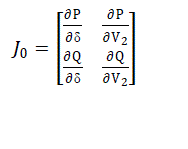 (4) (4) |
| The Jacobian is augmented by one column. Augmented Jacobian is given as (5). |
 (5) (5) |
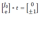
| A row vector, e with all elements equal to zero except one element chosen properly, which is equal to one, is appended to augmented Jacobian to normalize the tangent vector, t. Tangent vector is the vector of differentials. Value of one of the variable is mentioned as either +1 or -1. This particular variable is the continuation parameter. |
 (6) (6) |
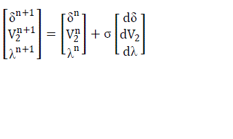
| Tangent vector, t = [dδ dV2 dλ ]t |
| Tangent vector is found using (6) and prediction is made using (7). |
 (7) (7) |
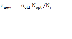
| where n is number of iteration, σ is specified step length. σ is modified in subsequent iterations according to the equation (8). |
 (8) (8) |
| where |
| Nopt = optimal number of corrector iterations |
| Nj = number of iterations required to correct the previous predicted solution |
| And then Newton Raphson method is used to correct the predicted value. |
| For a particular maximum value of continuation parameter chosen, λ, solution doesn’t exist. At this time continuation parameter is changed. Now, one of the state variables is chosen as continuation parameter. That’s why this is known as locally parameterized continuation. One way to select continuation parameter correctly is to start from λ and then after each iteration, state variable with largest tangent vector is chosen as continuation parameter. |
| Thus Continuation power Flow overcomes the problem of not converging at critical point by using continuation parameter technique. |
MAXIMUM LOADABILITY USING PSO
|
| A. PARTICLE SWARM OPTIMIZATION |
| Particle swarm Optimization is based on the behaviour of different organisms for example, school of fish, and flock of bird. It provides a search procedure based on population. Every Particle (individual) modifies its position in multidimensional space according to its own and neighbours’ experience. Best position of each particle is saved as local best position and best position among all these is recorded as global best position [10, 13]. Vel denotes velocity of each particle. The modified velocity and position of each particle is given by (9) and (10). |
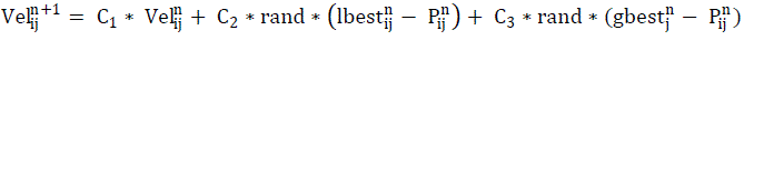 (9) (9) |
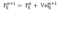 (10) (10) |
| where |
| ( i = 1,2…..s, j = 1,2 ……m) |
| s = number of particles in a group |
| m = number of members in a particle |
| C1 = inertia weight factor |
| C2 and C3 = acceleration constants |
| rand = uniform random values |
| Velij n = velocity of jth member of ith particle at nth iteration |
| Pij n = current position of jth member of ith particle at nth iteration |
| lbestij n = local best value of jth member of ith particle at nth iteration |
| gbestj n = global best value of jth member at nth iteration |
| Velocity should not be too slow or too high to avoid exploring not beyond local solution and bypassing good solutions respectively. Thus velocity of each particle should lie between a particular minimum and maximum value of velocity. Constants C2 and C3 make each particle to achieve local best and global best positions. These are set equal to 2 according to past experiences. Inertia weight is set according to the following equation (11). |
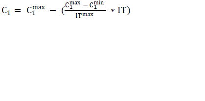 (11) (11) |
| where |
| ITmax = maximum no. of iterations |
| IT = current number of iteration |
| B. PROBLEM FORMULATION |
| Critical point (maximum real power demand, and the corresponding voltage), has been evaluated by simulating the problem as an optimization problem. It is formulated as shown in equation (12). |
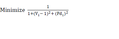 (12) (12) |
| where |
| Pdi = real power demand at the bus i |
| Vi = corresponding voltage at the bus i |
| Qdi is also varied at the bus i. It is varied in such a manner that the ratio of Qdi and Pdi remains constant, that is power factor remains constant as it is in the base case data. Load flow is used to find the voltage corresponding to the varied real power and reactive power demand. Demands for which load flow doesn’t converge are rejected by assigning a higher value to the voltage. |
| C. VARIABLE PARAMETERS |
| Real power demand is varied at bus i for which critical point is to be located. It is varied between a minimum and maximum value. Minimum value is taken as zero. Maximum value can be taken as suitably a high value number, say, 20 or 30 in per unit. |
| Ratio of reactive power and real power demand of ith bus of base case data is determined. Reactive power is then varied in the same ratio. |
| D. ALGORITHM |
| 1. Read the essential data. |
| 2. Velocities and initial set of solution of real power demand are generated randomly within their respective limits. The reactive power demand is computed keeping load power factor as constan |
| 3. Bus data is modified according to population generated. And then load flow solution is modified. |
| 4. Objective function values are calculated using eq. (12) for every particle of population. |
| 5. Update the local best and global best with the consideration of objective function values. |
| 6. Modify the new velocities using local best, global best using equation (9). Also calculate the real load demand using eq. (10) and compute reactive load demand for keeping power factor constant. |
| 7. If any violation in velocities and load demand, updated position, they are fixed at the respective limiting values. |
| 8. Compute load flow solution for new position, objective function value for each particle. |
| 9. If iteration no. is greater than the maximum no. of iteration then stop, otherwise go to step 5. |
RESULTS
|
| The proposed formulation is tested on different test systems namely, 6-Bus system, 4-Bus system and 2-Bus system. The data for 2-Bus, 4-Bus and 6-Bus are taken from [14], [15], [16], respectively. Results are compared with the Continuation Power Flow method. Maximum Loadability results for all the systems studied have been tabulated in Table 1 and the corresponding voltages at all buses of the systems at Maximum Loadability point are given in Table 2. The Table 2.1, Table 2.2, Table 2.3 corresponds to corresponding voltages at all buses of the systems at Maximum Loadability point on 2-bus, 4-bus and 6-bus systems respectively. P-V curves for some of the varied load buses obtained from Continuation Power Flow are depicted in Fig. 2. The Fig. 2(a), Fig. 2(b), Fig. 2(c) corresponds to P-V curve obtained from continuation power flow for a particular varying load on 2-bus, 4-bus and 6-bus systems respectively. The Table 1 suggests that results from CPF and presented formulation using PSO are comparable. |
CONCLUSION
|
| Maximum Loadability has been found for different load buses on different power systems using Particle Swarm Optimization. Results are compared with Continuation Power flow. P–V curves obtained from Continuation Power Flow have also been depicted in graphs. Thus it is found that Particle swarm optimization is a simple method to assess maximum loadability of the system. It doesn’t make use of any continuation parameter technique to find the critical point. It directly finds the critical point of the system. Result of PSO is found comparable with CPF. |
Tables at a glance
|
 |
|
| Table 1 |
Table 2 |
|
| |
Figures at a glance
|
 |
 |
| Figure 1 |
Figure 2 |
|
| |
References
|
- Custem T. V., “Voltage Instability: Phenomena, Countermeasures and Analysis Methods”, Proceedings of IEEE, vol. 88, pp. 208-227, 2000.
- Prabha K., “Power System Stability and Control”, Mc Graw –Hill, Power System, 1994.
- Atputharajah A., Saha T.K., “Power System Blackouts-Literature Review”, International Conference on Industrial and Information Systems, pp. 460-465, 2009.
- Ajjarapu V., “The Continuation Power Flow: A Tool for Steady State Voltage Stability Analysis”, IEEE Transactions on Power Systems, vol.7, pp. 416-423, 1992.
- Chiang H., Flueck A. J., Shah K.S., Balu N., “CPFLOW: A Practical Tool for Tracing Power System Steady - State Stationary Behavior due to Load and Generation Variations”, IEEE Transactions on Power Systems, vol. 10, pp. 623- 634, 1995.
- Yoshida H., Kawata K., Fukuyama Y., Takayama S., Nakanishi Y., “ A Particle Swarm Optimization for Reactive Power and Voltage control Considering Voltage Security Assessment” IEEE Transactions on Power Systems, vol. 15, pp. 1232-1239, 2000.
- Acharjee P., “Identification of Maximum Loadability Limit and Weak Buses using Security Constraint Genetic Algorithm”, International Journal of Electrical Power and Energy Systems, vol. 36, pp. 40-50, 2012.
- Gnanambal K., Babulal C. K., “Maximum Loadability Limit of Power System using Hybrid Differential Evolution with Particle Swarm Optimization”, International Journal of Electrical Power and Energy Systems, vol.43, pp. 150-155, 2012.
- El-Dib A. A., Youssef H. K. M. , El-Metwally M. M., Osman Z., “Maximum Loadability of Power Systems using Hybrid Particle Swarm Optimization”, Electric Power Systems Research, vol. 76, pp. 485-492, 2006.
- Kennedy J., Eberhart R.C., “Particle Swarm Optimization”, IEEE International Conference Proceedings on Neural Networks, vol. 4, pp.1942-1948, 1995.
- Valle Y. D., Venayagamoorthy G. K., Mohagheghi S., Hernandez J. C., Harley R. G., “Particle Swarm Optimization: Basic Concepts, Variants and Applications in Power Systems”, IEEE Transactions on Evolutionary Computation, vol. 12, pp. 171 - 195, 2008.
- Al Rashidi M.R., El-Harwary M.E., “A Survey of Particle Swarm Optimization Applications in Electric Power Systems”, IEEE Transactions on Evolutionary Computation, vol.13, pp. 913 - 918, 2009.
- Kothari D. P., Dhillon J.S., “Power System Optimization”, PHI Learning Private Limited, 2011.
- Ajjarapu V., “Computational Techniques for Voltage Stability Assessment and Control”, Springer, 2006.
- Grainger J. J., Stevenson W. D., “Power System Analysis”, Mc Graw – Hill,1994.
- Wood A. J., Wollenberg B. F., “Power Generation, Operation and Control”, John Wiley and Sons, 1996.
|