Keywords
|
| DC motor, PID controller, Tuning methods. |
INTRODUCTION
|
| DC machine is a highly versatile and flexible machine. It can satisfy the demands of load requiring high starting, accelerating and retarding torques. A dc machine is also easily adaptable for drives with range of speed control and fast reversal. They are widely used in industrial applications. The DC motors are used in rolling mills, in traction and in overhead cranes. They are also employed in many control applications as actuators and as speed or position sensors[2]-[6]. In such applications, as that of position sensors and robotics, drives? performance must precisely follow the desired performance. A number of control schemes such as proportional (P), proportional integral (PI), proportional derivative integral (PID), adaptive and fuzzy logic controller (FLCs) are used for control of speed of DC motors. The proposed controller system uses the PID control scheme for speed control of dc motor[1]. |
| PID controllers due to their simplicity are widely used in industrial applications for speed and position control of dc motor for several years. Due to its simplicity, clear functionality, applicability and ease of use offered, PID controllers are used in more than 95% of the industrial process control applications[9]. If the PID parameters are tuned properly they provide robust and reliable performance for most systems. In this paper, PID controller is used to control the speed of dc motor and hence its performance evaluation is done. As PID controllers require mathematical model of the system to be controlled, hence mathematical model of separately excited dc motor is derived and is simulated in Simulink[12]. |
MATHEMATICAL MODEL OF DC MOTOR
|
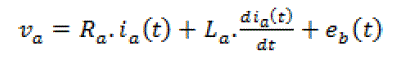
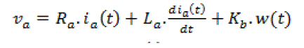
| In armature voltage control scheme for separately excited dc motors, voltage applied to armature is varied without varying the voltage applied to the field. Equivalent model of dc motor is shown in following figure.. |
 (1) (1) |
 (2) (2) |
 (3) (3) |
 (4) (4) |
| Where, Va = armature voltage (V) |
| Ra = armature resistance(Ω) |
| La = armature inductance (H) |
| Ia = armature current (A) |
| Eb = back emf (V) |
| W = angular speed (rad/s) |
| Tm= motor torque (Nm ) |
| θ = angular position of rotor shaft (rad) |
| Jm = inertia of rotor (Kg-m2) |
| Bm = viscous friction coefficient (Nms/rad) |
| KT = torque constant (N-m/A) |
| Kb = back emf constant (V/rad) |
| Let us combine the upper equations together: |
 (5) (5) |
 (6) (6) |
| Laplace transforms of (5) and (6) are |
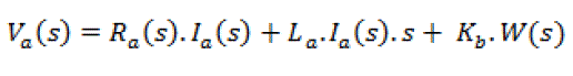 (7) (7) |
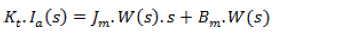 (8) (8) |
| If current is obtained from (8) and substituted in (7) we have |
 (9) (9) |
| Then the transfer function which relates rotor speed and applied armature voltage is given as: |
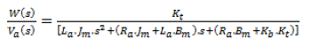 (10) (10) |
| Then the transfer function between shaft position and armature voltage at no-load is: |
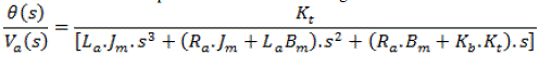 |
| The model of dc motor presented in this paper is simulated in MATLAB/Simulink, from its characteristic differential equation and it is shown in Figure 2 |
PID CONTROLLER
|
| Although being an old control technique, PID control scheme is extensively used in control systems for various control applications. The combination of proportional, integral and derivative control action is called PID control action and the controller is called three action controllers [7]. Although PD control deals neatly with the overshoot and rising problems associated with proportional control it does not reduce the problem with the steady-state error. Hence, PID controllers are used to reduce the steady-state error apart having the advantages of PD controllers. In PID controllers, we need to adjust three parameters i.e. proportional gain (Kp), integral gain (KI) and derivative gain (KD) to achieve the desired control performance. The PID controller system block diagram of this paper is shown in Fig 3 [5]. |
| The relationship between the input e(t) and output u(t) can be formulated in the following |
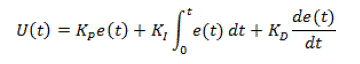 |
| The transfer function is expressed as follows |
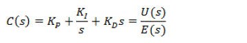 |
| The DC motor speed control using PID controller system block diagram is shown in Fig 4 |
DESIGN OF PID CONTROLLER
|
| There are many methods proposed for tuning of PID controller: |
| • Process reaction curve (Open-loop) ? |
| • Ziegler Nichols method (Closed-loop) ? |
| • Tyreus and Luyben ? |
| Process reaction curve (Open-loop): This is a manual procedure which is based on measuring the step response of the system .The input variable r(t) is changed from to ;the output c(t) is monitored carefully and the step response recorded on a chart recorder in Fig 6. Here r(t) should be as small as possible. On the recorded output, draw a tangent to enable the following measurements [4]: |
| • Effective time delay in ? the system response „L?; |
| ? Recorded output change, M=C1-C0; |
| ? Measurement of „T?; |
| • P = percent change in correction unit |
| ? M (measured variable) = percent of full scale range |
| • R (reaction rate) = maximum gradient of the graph |
| Empirical relationships in terms of for P, PI, and PID are by process reaction curve is given in Table.1 |
| Ziegler Nichols method (Closed-loop): Another method to tune PID parameters is Ziegler-Nichols frequency response method. The procedure is as follows: |
| 1. Increase KP until system response oscillates with a constant amplitude and record that gain value as Ku (ultimate gain). |
| 2. Calculate the oscillation period and record it as Tu |
| 3. Tune parameters using Table 2 [13] |
| Tyreus and Luyben: A modification to the above Ziegler-Nichols tuning parameters was made by Tyreus and Luyben shown in Table.3 [4] |
DESIGN OF REAL TIME PID CONTROLLER
|
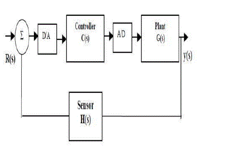
| Figure 6 shows the block diagram of the real-time digital PID controller, where R(s) is the reference input, y(s) is the system output, C(s) is the controller transfer function, and H(s) is the feedback loop (sensor) transfer function. There are two possible ways to control the speed of the motor viz. open loop control and closed loop control. In open loop control, the control value is not dependent on the output or the speed of the motor, whereas in closed loop control in which the control value is dependent on the speed of the motor. In the real-time speed control approach a closed loop speed control with a digital PID controller is designed. A potentiometer is used as the reference command signal to set the input voltage at various levels as required. Further, the control value obtained from microcontroller is utilized to generate the average output voltage for adjusting the duty cycle in order to maintain constant motor speed. |
 |
| Discrete PID controller structure |
There are two possible ways to control the speed of the motor viz. open loop control and closed loop control. In open
loop control, the control value is not dependent on the output or the speed of the motor, whereas in closed loop
control in which the control value is dependent on the speed of the motor. In the real-time speed control approach a
closed loop speed control with a digital PID controller is designed. A potentiometer is used as the reference
command signal to set the input voltage at various levels as required. Further, the control value obtained from
microcontroller is utilized to generate the average output voltage for adjusting the duty cycle in order to maintain
constant motor speed. |
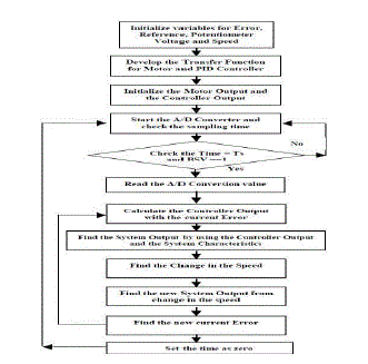 |
| Figure shows the flowchart of the algorithm that was developed. The controller equations are loaded into the flash memory of the first microcontroller. For simulation purposes, the transfer function equations of the motor were loaded into the flash memory of the second microcontroller. At first, the system output from the transfer function was utilized to generate the controller value from the microcontroller1. The motor speed is read at fixed intervals using the A/D converter of microcontroller1, and the digital inputs were converted into a CAN data frame for two bytes. The object consists of these two bytes and an 11-bit identifier 0x111. This data is then transferred to the CAN bus which is identified by the CAN bus monitor as the system output. Microcontroller2 waits for a CAN message with identifier 0x111.Therefore, as soon as the above object with identifier 0x111 appears on the CAN bus, it is captured by microcontroller2. Microcontroller uses this received data to generate the controller value. The controller value is calculated using the difference between the reference speed (based on the potentiometer setting) and the actual speed measured by microcontroller1. This error is then used to generate the PID constants, which in turn develops the duty cycle (D) equivalent for the discrete closed loop control Above figure shows the simulation model of control system of speed control of dc motor using PID control. Difference between the reference speed and the actual motor speed is provided as an input to the PID controller. |
| As the error input increases controller adjusts its output parameters accordingly so as to reduce the error between the desired and actual speed. |
| A typical procedure to tune a PID controller using Ziegler Nichols method would be: |
| 1. Increase KP until system response oscillates with a constant amplitude and record that gain value as Ku (ultimate gain). |
| 2. Calculate the oscillation period and record it as Tu [11] |
| Figure.1 above shows the speed response of dc motor using PID controller when step input is applied as reference signal. As it is clear from the response curve that an overshoot is obtained along with certain oscillations around reference signal. However overshoot can be reduced by increasing the derivative gain but the rise time also increases as a consequence. Hence, there exists a compromise between overshoot and the speed of response i.e. rise time which means that we have to sacrifice one for improving another. |
| From the above graph of speed response following parameters can be calculated to evaluate the performance of PID controller: |
CONCLUSIONS
|
| In this paper PID controller is designed for speed control of dc motor. From the analysis been done it is clear that PID is a simple controller based on the mathematical model of the system to be controlled. It successfully overcomes the drawback of proportional-derivative (PD) controller of steady-state error as steady-state error is zero in PID controllers. However while reducing steady-state error to zero an overshoot is observed. However overshoot can be reduced by increasing the derivative gain but the rise time also increases as a consequence. Hence, there exists a compromise between overshoot and the speed of response i.e. rise time which means that we have to sacrifice one for improving another. Overall, PID controller gives best speed response of all the linear controllers of its class. It is simple to implement and control the process using PID controllers. |
Tables at a glance
|
 |
|
|
|
| Table 1 |
Table 2 |
Table 3 |
Table 4 |
|
Figures at a glance
|
 |
 |
 |
 |
 |
| Figure 1 |
Figure 2 |
Figure 3 |
Figure 4 |
Figure 5 |
|
 |
 |
 |
 |
| Figure 6 |
Figure 7 |
Figure 8 |
Figure 9 |
|
References
|
- EssamNatsheh and Khalid A. Buragga, “Comparison between Conventional and Fuzzy Logic PID Controllers for Controlling DC Motors,” International Journal of Computer Science Issues, Vol. 7, Issue 5, September 2010.
- Ankit Rastogi and PratibhaTiwari,”Optimal Tuning of Fractional Order PID Controller for DC Motor Speed Control Using Particle Swarm Optimization,” International Journal of Soft Computing and Engineering, Volume-3, Issue-2, May 2013
- Mehdi GhazaviDozein, Amin Gholami and Mohsen Kalantar,” Speed Control of DC Motor Using Different Optimization Techniques Based PID Controller” Journal of Basic and Applied Scientific Research, J. Basic. Appl. Sci. Res., 2(7)6488-6494, 2012
- Salim, Sunil Kumar and JyotiOhri, “LabVIEW Based DC Motor and Temperature Control Using PID Controller,”Volume 3, Issue 5, May 2013.
- MeghaJaiswal and MohnaPhadnis, “Speed Control of DC Motor Using Genetic Algorithm Based PID Controller,” International Journal of Advanced Research in Computer Science and Software Engineering,Volume 3, Issue 7, July 2013.
- Dingy¨uXue, YangQuan Chen and Chunna Zhao, “Fractional Order PID Control of A DC-Motor with Elastic Shaft:A Case Study,” Proceedings of the 2006 American Control Conference Minneapolis, Minnesota, USA, June 14-16, 2006
- R. Caponetto, L. Fortuna, and D. Porto, “A new tuning strategy for a non- integer order PID controller,” IFAC2004, Bordeaux, France, 2004
- Liu Fan, Er Meng Joo” Design for Auto-tuning PID Controller Based on Genetic Algorithms” NanyangTechnological University Singapore IEEE Trans on ICIEA 2009
- M. Zamani, N. Sadati and M. K. Ghartemani, 2009. Design of an H∞ PID Controller Using Particle Swarm Optimization, International Journal of Control, Automation, and Systems, vol. 7, pp. 273-280.
- Zhang Lin, Song Yin, “Design of PID Temperature Controlling System Based on Virtual Instrument Technique”, The Eighth International Conference on Electronic Measurement and Instruments, 2005
- DeepyamanMaiti, Sagnik Biswas and Amit Konar, “Design of a fractional order PID controller using particle swarm optimization technique,” Proc. ReTIS"08, 2008.
|