Keywords
|
| Power system harmonic, Active power filter, Harmonics mitigation, Power quality, control strategy |
INTRODUCTION
|
| Power electronic appliances are used widely in industrial, commercial and consumer environment. These appliances generate harmonics and reactive power in the utility system. The improvement of power quality by reducing harmonics has become an important issue nowadays [1-4]. Conventionally, passive LC filters have been used to eliminate line current harmonics and to improve the power factor. But the passive filters have many disadvantages, such as fixed compensation, large size and resonance problems. To solve above mentioned problems, active power filters were introduced. |
| Power quality can be defined as the interaction of electrical power with electrical equipment. If electrical equipment operates correctly and reliably without being damaged or stressed, we would say that the electrical power is of good quality. On the other hand, if the electrical equipment malfunctions, is unreliable, or is damaged during normal usage, we would suspect that the power quality is poor. Power quality determines the fitness of electrical power to consumer devices. The presence of harmonic waveforms in power system is the main cause of power quality problems. Harmonics have a number of undesirable effects on the distribution system. It causes excessive voltage distortion, increased resistive losses or voltage stresses, reductions in ac motor efficiency and product quality etc in the power system. With the widespread use of harmonic generating devices, the control of harmonic currents to maintain a high level of power quality is becoming increasingly important. An effective way for harmonic suppression is the harmonic compensation by using active power filter. Active power filters are considered as a feasible solution for reducing current harmonics and reactive power due to their small size, no requirement for tuning and stable operation. |
| The basic compensation principles of active filters were proposed around 1970. They act as harmonic current source to provide an effective result to eliminate the harmonic currents and also to compensate the reactive power. |
A. Power system harmonics
|
| Power system harmonics are integer multiples of the fundamental power system frequency. Power system harmonics are created by non-linear devices connected to the power system. Harmonics are voltage and current frequencies riding on top of the normal sinusoidal voltage and current waveforms. The presence of harmonics (both current and voltage) is viewed as `pollution' affecting the operation of power systems. |
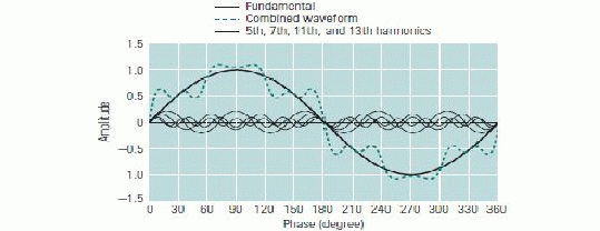
| The most common source of harmonic distortion is electronic equipment using switch-mode power supplies, such as computers, adjustable-speed drives, and high-efficiency electronic light ballasts. Harmonic waveforms are characterized by their amplitude and harmonic number. When a sinusoidal voltage is applied to a certain type of load, in which the load cause the current to vary disproportionately with the voltage during each cyclic period. These are classified as nonlinear loads, and the current taken by them will be a non sinusoidal waveform. When there is significant impedance in the path from the power source to a nonlinear load, these current distortions will also produce distortions in the voltage waveform at the load. Waveform distortion can be mathematically analyzed to show that it is equivalent to superimposing additional frequency components onto a pure sine wave (figure 2.1). These frequencies are harmonics (integer multiples) of the fundamental frequency, and can sometimes propagate outwards from nonlinear loads, causing problems elsewhere on the power system. |
| The harmonics generated by the most common non-linear loads have the following properties: |
| • Lower order harmonics tend to dominate in amplitude |
| • If the waveform has half-wave symmetry there are no even harmonics |
| • Harmonic emissions from a large number of non-linear loads of the same type will be added. |
| The figure 2.1 shows the effect of harmonics on normal voltage or current waveform [5]. Odd harmonics waveforms contribute more to power system instability. In the figure the combined waveform shows the result of adding the harmonics on to the fundamental. |
| Harmonics in power systems can become the source of a variety of unwelcome effects. For example, harmonics can cause signal interference, over voltages, data loss, and circuit breaker failure, as well as equipment heating, malfunction, and damage. Any distribution circuit serving modern electronic devices will contain some degree of harmonic frequencies. The greater the power drawn by nonlinear loads, cause greater the level of voltage distortion. Potential problems (or symptoms of problems) attributed to harmonics include: |
| • Malfunction of sensitive equipment |
| • Random tripping of circuit breakers |
| • Flickering lights |
| • Very high neutral currents |
| • Overheated phase conductors, panels, and transformers |
| • Premature failure of transformers and uninterruptible power supplies (UPSs) |
| • Reduced power factor |
| • Reduced system capacity (because harmonics create additional heat, transformers and other distribution equipment cannot carry full rated load) |
| In addition, the harmonic currents produced by nonlinear loads can interact adversely with a wide range of power system equipment, most notably capacitors, transformers, and motors, causing additional losses, overheating, and overloading. These harmonic currents can also cause interferences with telecommunication lines and errors in metering devices. Because of the adverse effects that harmonics have on power quality, Standard has been developed to define a reasonable framework for harmonic control. Harmonic distortion in power distribution systems can be suppressed using different approaches. One among them is the use of active power filters. |
B. Active power filters (APF)
|
| Harmonic distortion in power distribution systems can be suppressed mainly by, passive and active filtering. The passive filtering is the simplest conventional solution to mitigate the harmonic distortion. The uses of passive elements do not always respond correctly to the dynamics of the power distribution systems. Passive filters are known to cause resonance, thus affecting the stability of the power distribution systems. Frequency variation of the power distribution system and tolerances in components values affect the passive filtering characteristics. As the regulatory requirements become more stringent, the passive filters might not be able to meet future revisions of a particular Standard. This may required a retrofit of new filters. |
| Remarkable progress in power electronics had spurred interest in Active Power Filters (APF) for harmonic distortion mitigation. Active filtering is a relatively new technology, practically less than four decades old. The basic principle of APF is to utilize power electronics technologies to produce specific current components that cancel the harmonic current components caused by the nonlinear load. |
| APFs have a number of advantages over the passive filters. First of all, they can suppress not only the supply current harmonics, but also the reactive currents. Moreover, unlike passive filters, they do not cause harmful resonances with the power distribution systems. Consequently, the APFs performances are independent on the power distribution system properties. Active filtering is a relatively new technology, practically less than four decades old. There is still a need for further research and development to make this technology well established. |
C. The working of APF
|
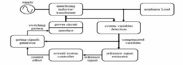
| The Figure 2.2 shows the components of a typical APF system and their connections. The compensation reference signal from the estimator drives the overall system controller. This in turn provides the control for the gating signal generator. The output of the gating signal generator controls the power circuit via a suitable interface [6]. |
| Finally, the power circuit in the generalized block diagram can be connected in parallel, series or parallel/series configurations depending on the interfacing inductor/transformer used. An unfavorable but inseparable feature of APF is the necessity of fast switching of high currents in the power circuit of the APF. |
| An active power filter can be considered as a compensator for power system harmonics. The working of active power filter consists of mainly three stages [7]. They are: |
| 1. Signal conditioning |
| 2. Derivation of compensating signal. |
| 3. Generation of gating signal. |
| Signal conditioning refers to the detection or sensing of harmonics in the power distribution line. As shown in Figure 2.2, the reference signal to be processed by the controller is the key component that ensures the correct operation of APF. |
| The reference signal estimation is initiated through the detection of essential voltage/current signals to gather accurate system variables information. The voltage and current variables in power system is sensed by using potential transformers, current transformers, isolation amplifiers etc. The voltage variables to be sensed are AC source voltage, DC-bus voltage of the APF, and voltage across interfacing transformer. Typical current variables are load current, AC source current, compensation current and DC-link current of the APF. Based on these system variables feedbacks, reference signals estimation in terms of voltage/current levels are estimated in frequency-domain or time-domain. |
| The next stage is the derivation of compensating signal from the disrupted wave consists of both fundamental wave and the harmonic content. It can be done by two different methods-frequency domain approach and time domain approach. Frequency domain approach use Fourier transformation method for this purpose. While Time domain approach uses different methods like Instantaneous Reactive-Power Theorem, Synchronous-Reference-Frame Theorem, Synchronous Detection Theorem, Sine-Multiplication Theorem, notch filter method etc. |
| The third stage is the generation of gating signal for harmonic suppression. So many control techniques like space Vector PWM, repetitive control, hysteresis current control, one-cycle control, dead-beat control, sliding mode control, fuzzy control and the artificial neural network method have been introduced and applied to various configurations of active power filters. Gating signal generator in the general block diagram of APF is used for this purpose. |
D. Classifications of APF
|
| APF can be connected in several power circuit configurations as illustrated in the block diagram shown in Figure 2.3. In general, they are divided into three main categories, namely shunt APF, series APF and hybrid APF [6][8]. |
| 1) Shunt Active Power Filter |
| This class of filter configurations is the most important and most widely used type in active filtering applications. It is connected to the main power circuit, as shown in the single-line diagram of Fig.2.4. |
| The purpose is to cancel the load current harmonics fed to the supply. It can also contribute to reactive-power compensation and balancing of three-phase currents, as mentioned above. Parallel filters have the advantage of carrying only the compensation current plus a small amount of active fundamental current supplied to compensate for system losses. It is also possible to connect several filters in parallel for higher currents, which makes this type of circuit suitable for a wide range of power ratings. |
| 2) Series Active Power Filter |
| The active filter in this configuration produces a PWM voltage waveform which is added or subtracted, on an instantaneous basis, to/from the supply voltage to maintain a pure sinusoidal voltage waveform across the load. The main power-circuit configuration is shown in Fig.2.5. |
| The inverter configuration accompanying such a system is a voltage-fed inverter without any current-control loops. Series active filters are less common industrially, than parallel active filters. This is because of the main drawback of series circuits, namely that they have to handle high load currents, which increases their current rating considerably compared with parallel filters, especially in the secondary side of the coupling transformer. |
| The main advantage of series filters over parallel ones is that they are ideal for eliminating voltage-waveform harmonics, and for balancing three-phase voltages. This, in fact, means that this category of filter is used to improve the quality of the system voltage for the benefit of the load. It provides the load with a pure sinusoidal waveform, which is important for voltage-sensitive devices. |
| 3) Hybrid Active Power Filters |
| Technical limitations of conventional APFs can be overcome with hybrid APF configurations. They are typically the combination of basic APFs and passive filters. Hybrid APFs, inheriting the advantages of both passive filters and APFs provide improved performance and cost-effective solutions. The idea behind this scheme is to simultaneously reduce the switching noise and electromagnetic interference. |
| The idea of hybrid APF has been proposed by several researchers. In this scheme, a low cost passive high-pass filter (HPF) is used in addition to the conventional APF. The harmonics filtering task is divided between the two filters. The APF cancels the lower order harmonics, while the HPF filters the higher order harmonics. The main objective of hybrid APF, therefore is to improve the filtering performance of high-order harmonics while providing a cost-effective low order harmonics mitigation. |
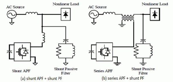
| Nowadays various hybrid APFs using in electronic industry, but the two most prominent ones are shown in Figure2.6. Figure2.6 (a) is the system configuration of the hybrid shunt APF. Both the shunt APF and passive filter are connected in parallel with the nonlinear load.The function of the hybrid APF can thus be divided into two parts: the low-order harmonics are cancelled by the shunt APF, while the higher frequency harmonics are filtered by passive HPF. This topology lends itself to retrofit applications with the existing shunt APF. |
| Figure 2.6(b) shows the system configuration of hybrid series APF, in which the series APF is coupled to the distribution line by an interfacing transformer [4]. The shunt passive filter consists of one or more single-tuned LC filters and/or a HPF. |
REFERENCE SIGNAL ESTIMATION TECHNIQUES
|
| One of the most discussed software part (in the case of a DSP implementation) of an active filter is the harmonic detection method. In brief, it represents the part that has the capability of determining specific signal attributes from an input signal (that can be voltage, current or both) by using a special mathematical algorithm. |
| Different algorithms emerged for the harmonic detection, which led to a large scientific debate on which part the focus should be put on, the detection accuracy, the speed, the filter stability, easy and inexpensive implementation, etc. The classification of these methods can be done relative to the domain where the mathematical model is developed. Thus, two major directions are described here, the time domain and the frequency-domain methods. |
| Table 3.1 illustrates the considered reference signal estimation techniques [9]. They cannot be considered to belong to the control loop since they perform an independent task by providing the controller with the required reference for further processing. This section presents the considered reference signal estimation techniques, providing for each of them a short description of their basic features. |
A. Frequency Domain Approach
|
| Reference signal estimation in frequency-domain is suitable for both single- and three- phase systems. They mainly derived from the principle of Fourier analysis as follows. |
| In principle, Fourier Transform (conventional or Fast Fourier Transform (FFT)) is applied to the captured voltage/current signal. The harmonic components of the captured voltage/current signal are first separated by eliminating the fundamental component. Inverse Fourier Transform is then applied to estimate the compensation reference signal in time domain. |
| The main drawback of this technique is the accompanying time delay in system variables sampling and computation of Fourier coefficients. This makes it impractical for real-time application with dynamically varying loads. Therefore, this technique is only suitable for slowly varying load conditions. In order to make computation much faster, some modifications was proposed and practiced later. In this modified Fourier-series scheme, only the fundamental component of current is calculated and this is used to separate the total harmonic signal from the sampled load-current waveform. |
B. Time Domain Approaches
|
| Time-domain approaches are based on instantaneous estimation of reference signal in the form of either voltage or current signal from distorted and harmonic-polluted voltage and current signals. These approaches are applicable for both single-phase and three-phase systems except for the synchronous-detection theorem and synchronous-reference-frame theorem which can only be adopted for three-phase systems [9]. |
| 1) Instantaneous power theory |
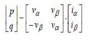
| Instantaneous power theory (and variants) determines the harmonic distortion from the instantaneous power calculation in a three-phase system, which is the multiplication of the instantaneous values of the currents and voltages. The calculations may be done in αβ-coordinates as in the below equation. |
 (1) (1) |
| The values of the instantaneous power p and q, which are the real respective imaginary powers, contain dcand ac components depending on the existing active, reactive and distorted powers in the system. The dc components of p and q represent the active and reactive powers and must be removed with high-pass filters (with a cutting frequency between 5 Hz - 35 Hz) to retain only the ac-signals. According the instantaneous reactive power theory, p and q, are decomposed into instantaneous real and imaginary powers, respectively. The ac-components calculated back to the abc-frame represent the harmonic distortion, which is given as the reference for the current controller. Again the presence of the numerical filters has influence in the dynamic and the accuracy for the entire APF[9][11]. |
| The calculation in this block diagram may affected, if the system has zero sequence component due to an existing unbalance. Therefore, also a p0 component must be added to provide a complete analysis. Other techniques based on the same principle improve different other feature, as like the cancellation of the neutral currents, the minimization of the energy storage element, the pre-processing of the input voltages to keep only the positive sequence. |
| 2) Synchronous dq Frame |
| Synchronous fundamental dq-frame is derived from the space vector transformation of the input signals, which initially are achieved in the abc-coordinates (stationary reference frame) from the sensors and then transformed into the dq-coordinates (rotating reference frame with fundamental frequency) by means of the Park transformation (below equation). Here the dq frame rotates with the fundamental angular frequency. And in this frame the fundamental currents are appeared as dc components and the harmonics as ac-signals [9][12]. |
| Let id, iq and ia, ib, ic are the currents in the dq-frame and abc-frame respectively; θ is the reference angle. Then, id and iq can be represented as shown below, |
 (2) (2) |
| The active and reactive components of the three-phase system are represented by the direct and quadrature components respectively. In this theorem, the fundamental components are transformed into DC quantities which can be separated easily through filtering. Thus, the detection of the harmonics becomes a matter of removing the dc-signal with a High-Pass Filter (with a cutting frequency between 25 Hz - 120 Hz). |
| This theorem is applicable only to three-phase system. The system is very stable since the controller deals mainly with DC quantities. The computation is instantaneous but incurs time delays in filtering the DC quantities. |
CONTROL TECHNIQUES FOR ACTIVE POWER FILTER
|
| The aim of APF control is to generate appropriate gating signals for the switching transistors based on the estimated compensation reference signals. The performance of an APF is affected significantly by the selection of control techniques. Therefore, the choice and implementation of the control technique is very important for the achievement of a satisfactory APF performance [10]. A variety of control techniques, such as linear control, digital deadbeat control, hysteresis control, etc. are implemented for the APF applications. This section briefly describes the considered control techniques and their basic feature. |
A. Linear control technique
|
| The linear control of APF is accomplished by using a negative-feedback system as shown in figure 4.1(a) [4]. In this control scheme, the compensation current (if) or voltage (vf) signal is compared with its estimated reference signal (ifref or vfref) through the compensated error amplifier to produce the control signal. |
| The resulting control signal is then compared with a saw tooth signal through a pulse width modulation (PWM) controller to generate the appropriate gating signals for the switching transistor. The frequency of the repetitive saw tooth signal establishes the switching frequency. This frequency is kept constant in linear control technique. As shown in fig.4.1 (b) the gating signal is set high when the control signal has a higher numerical value than the saw tooth signal and via versa. |
| Generally, the Nyquist stability criterion and the Bode plots are used to determine the appropriate compensation in the feedback loop for the desired steady state and transient responses. With analogue PWM circuit, the response is fast and its implementation is simple. Nevertheless, due to inherent problem of analogue circuitry, the linear control technique has an unsatisfactory harmonic compensation performance. This is mainly due to the limitation of the achievable bandwidth of the compensated error amplifier. |
B. Hysteresis Control Technique
|
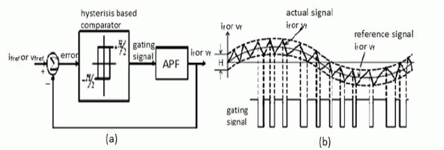
| The control of APF can be realized by the hysteresis control technique. It imposes a bang-bang type instantaneous control that forces and APF compensation current ( if ) or voltage (vf ) signal to follow its estimated reference signal (ifref or vfref ) within a certain tolerance band. This control scheme is shown in a block diagram form in Figure4.2 .In this control scheme, a signal deviation (H) is designed and imposed on ifref or vfref to form the upper and lower limits of a hysteresis band. The if or vf is then measured and compared with ifref or vfref; the resulting error is subjected to a hysteresis controller to determine the gating signals when exceeds the upper or lower limits set by (estimated reference signal + H/2) or (estimated reference signal – H/2). As long as the error is within the hysteresis band, no switching action is taken. Switching occurs whenever the error hits the hysteresis band. |
| The APF is therefore switched in such a way that the peak-to-peak compensation current/voltage signal is limited to a specified band determined by H as illustrated in fig4.2 (a). Hysteresis current controller with a fixed H is implemented is known to be more popular [4]. To obtain compensation current (if) with switching ripples as small as possible, the value of H can be reduced. But it results in higher switching frequency and increase losses on the switching transistors. The advantages of using the hysteresis current controller are its excellent dynamic performance and controllability of the peak-to-peak current ripple within a specified hysteresis band. The main drawback is that it produces uneven switching frequency. Consequently, difficulties arise in designing the passive HPF. Furthermore, there is possibly generation of unwanted resonances on the power distribution system besides; the irregular switching also affects the APF efficiency and reliability. |
CONCLUSION
|
| In modern electric power supply distribution systems, there is a sharp rise in the use of single phase and three phase non-linear loads which causes harmonic disturbances. Active power filters are the emerging devices, which can perform the job of harmonic elimination properly. First the harmonic disturbances are detected from the power line using transducers, and then harmonic waveform is separated from the fundamental sine wave using reference signal estimation techniques. The PWM signals for controlling purpose are then generated using any one of control signal generation schemes. Thus an APF provide harmonic elimination with better controlling methods. |
| The paper begins with a brief discussion on harmonic distortion problems and its impact on power system. Then an evaluation of the commonly used methods for harmonic detection and generation of control signals in active power filter applications are mentioned. The review and classification of this work shows that there has been a significant increase in interest of active filters and associated control methods. Control circuits constitute a minor portion of the total cost of active filters. This is due to increasing concern about power quality and the availability of suitable powerswitching devices. |
Tables at a glance
|
 |
| Table 1 |
|
| |
Figures at a glance
|
 |
 |
 |
 |
 |
| Figure 1 |
Figure 2 |
Figure 3 |
Figure 4 |
Figure 5 |
 |
 |
 |
 |
 |
| Figure 6 |
Figure 7 |
Figure 8 |
Figure 9 |
Figure 10 |
|
| |
References
|
- S.L.Clark,P.Famouri, W.L.Cooley, “Elimination of supply harmonics”, IEEE Industry Applications Magazine B March/April I997.
- Luis A. Morán, Juan W. Dixon, José R. Espinoza, Rogel R. Wallace, “Using active power filters to improve power Quality”, IEEE Transactions on, vol. 40, pp. 232-241, 2004.
- J.L. Hernández, M.A. Castro, J. Carpio and A. Colmenar, “Harmonics in Power Systems”, International Conference on Renewable Energies and Power Quality (ICREPQ’09) Valencia (Spain), 15th to 17th April, 2009.
- BudwalAmrinder Singh, Chinmaya R. Chute, Shiva Gourishetti, “ Harmonics Effect on Power Quality and its Mitigation Techniques using Active Power Filter”, Proceedings of Third Biennial National Conference, NCNTE- 2012, Feb 24-25.
- Institute of Electrical and Electronics Engineers (IEEE), Standard 519-1992, “IEEE Recommended Practices and Requirements for Harmonic Control in Electric Power Systems” (1992)
- Zainal Salam, Tan Perng Cheng and AwangJusoh, “Harmonics Mitigation Using Active Power Filter: A Technological Review”, ELEKTRIKA, VOL. 8, NO. 2, 200.6, 17-26.
- Park ki-won, “A Review of active power filters”, R&D Center, POSCON.
- M.E-Habrouk, M.K.Darwish and P.Mehta, “Active power filters: A review”, IEEE Proc.-Elertr. Power Appl., Vol. 147, No. 5, September 2000
- Lucian Asiminoaei, FredeBlaabjerg, Steffan Hansen, “Evaluation of Harmonic Detection Methods for Active Power Filter Applications”, Institute of Energy Technology, Denmark.
- R.Zahira, A.PeerFathima, “A Technical Survey on Control Strategies of Active Filter for Harmonic Suppression”, Procedia Engineering 30 (2012) 686 – 693.
- P. Salmerón, R.S. Herrera,” Instantaneous reactive power theory—A general approach to poly-phase systems”, Electric Power Systems Research 79 (2009) 1263–1270.
- K. G. Firouzjah, A. Sheikholeslami, M. R. KaramiMollaei, M. Khaleghi,” A New Harmonic Detection Method for Shunt Active Filter Based on Wavelet Transform”, Journal of Applied Sciences Research, 4(11): 1561-1568, 2008
|