Keywords
|
| Brushless Motors, Permanent Magnet Motors, Trapezoidal Control, Sinusoidal Control, Field Oriented Control, Pulse Width Modulation |
INTRODUCTION
|
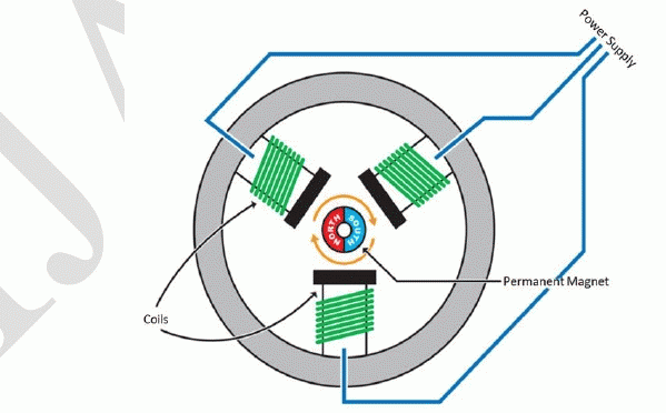
| In its simplest form, a Brushless Motor consists of a Permanent Magnet which acts as the rotor. The rotor is surrounded by three equally spaced fixed stator windings as shown in figure 1. The current flow in each winding produces a magnetic field vector which sums up with each other to form a resultant magnetic field. Torque is produced in the motor by the attraction or repulsion between this net stator magnetic field and the magnetic field produced by the permanent magnet, i.e. rotor. By controlling the current flow in the three windings, a magnetic field of arbitrary direction and magnitude can be produced by the stator and thereby, the torque produced can be controlled. The conventional Brushed motors commutate itself with the use of a mechanical commutator whereas brushless motors need electronic commutation for the direction control of current through the windings. |
| For any position of the rotor, there is an optimal direction for the net stator field which maximizes the torque produced [1]. If the net stator field and the rotor field are in the same direction then no torque will be produced. This is because the forces produced by the interaction of the fields act in line with the axis of rotation of the rotor and only leads to compression of the motor bearings, rather than rotation. If the stator field is perpendicular to the rotor field, then maximum torque is produced. |
| Any stator field can be represented as a resultant of two vector components, the orthogonal (quadrature) component which is responsible for producing torque, and the parallel (direct) component which produces undesired heat and compression forces. Hence, an ideal drive should aim to minimize the parallel component while maximizing the quadrature component. |
| The stator field is produced by current flow in three equally spaced windings that are mechanically located 120o apart. Hence, they each produce a field vector component that is oriented 120o from each other. The mathematical models for Permanent Magnet Motors are in terms of winding currents rather than stator magnetic field since they are easier to measure. Current Space Vectors are used to model the stator fields in terms of winding currents. The current space vector for a given winding has a magnitude proportional to the current flowing through the winding and a direction of the field produced by that winding. This allows us to represent the total stator field as a current space vector that is the vector sum of three current space vector components of the windings. To simply put, the resultant current space vector is the current that would need to flow in a single fictitious winding in order to produce the same stator field direction and magnitude as the combination of three real currents through real stator windings. |
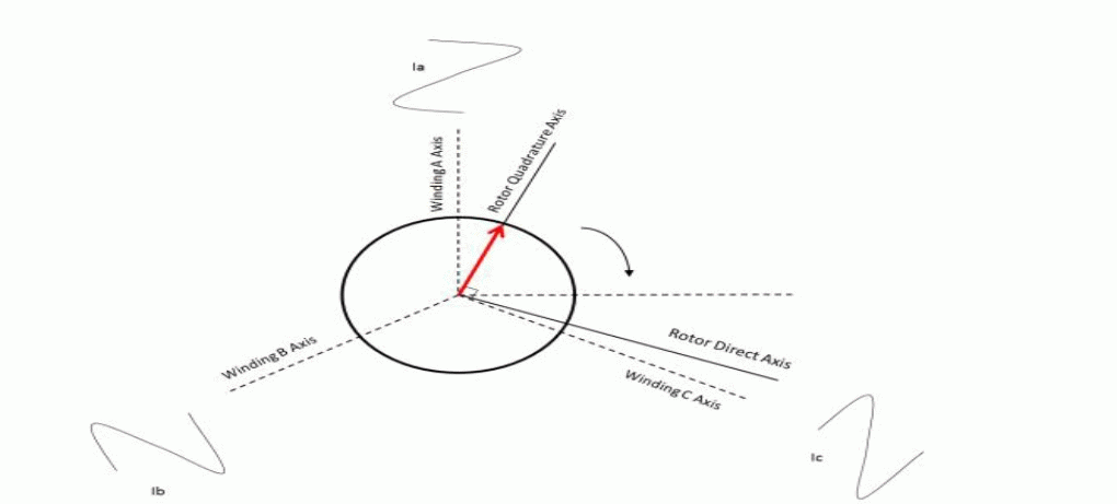
| Just like the stator field, the current space vector too can be broken down into quadrature and direct axis components. The orthogonal (quadrature) current component produces a field at right angles to the rotor magnet and therefore results in torque, while the parallel (direct) current component produces a field that is aligned with the rotor magnet and produces no torque. Hence, the aim of a control algorithm is to reduce the direct current components so as to minimize losses. The Current Space Vector is illustrated in figure 2, where the three windings are named A,B& C respectively. |
| To produce constant smooth torque, the stator current space vector should ideally be constant in magnitude and should turn with the rotor so as to always be in the quadrature direction, irrespective of rotor angle and speed. To achieve this, various control algorithms have been experimented and developed with varying degrees of success. |
| The nature of their construction lends permanent magnet motors several advantages over conventional induction motors, such as: |
| • Elimination of field copper loss |
| • Higher power density |
| • Lower rotor inertia |
| • Compact size |
| • Fast dynamic response |
| • Overall higher efficiency |
| New Developments and research in the fields of magnetic and insulating materials, as well as control strategies have further broadened the appeal and viability of these motors in various applications [2]. They are becoming increasingly popular in applications such as Traction Work, Electric/Hybrid Vehicles [3] and even in Medical Applications. |
COMPARISON OF PMSM AND BLDC MOTORS
|
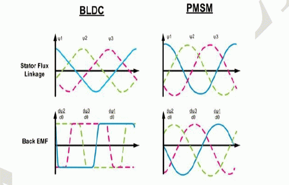
| There are primarily two main types of Brushless motors, namely- The Brushless DC Motor (BLDC), and the Permanent Magnet Synchronous motor (PMSM). They both share the same basic construction, consisting of permanent magnets on the rotor and windings on the stator. However, one principal difference is that the coils in the stator are evenly wound in a BLDC motor, and in the case of PMSM are wound in a symmetrical fashion [2]. As a result, the Back-EMF generated in a BLDC motor is trapezoidal in nature as shown in figure 3, and Sinusoidal in nature in PMSM motors. Consequently, the PMSM motors are more efficient and produce less noise and torque ripple. |
| However, the inherent advantages of a PMSM motors does necessitate more complex control algorithms. |
CONTROL TECHNIQUES
|
| Numerous brushless motor control techniques are available today. They can primarily be classified into three categories, namely: Trapezoidal, Sinusoidal and Field Oriented Control. |
A. TRAPEZOIDAL CONTROL
|
| One of the simplest and common methods for controlling Brushless DC motors (BLDC) is Trapezoidal Control. As mentioned earlier, the stator consists of three stator windings which act as terminals. In this method, current is controlled through two terminals at a time, during which the third terminal is electrically disconnected from the source. To measure the rotor position, Hall Effect sensors are usually embedded into the motor. At any instant of time, current of equal magnitude is flowing in two of windings while the third one is zero. Due to this, the current space vector can be one of six different possible directions as shown in figure 4. |
| As the motor rotates, the current to the motor terminals is electrically switched (commutated) for every 60o of rotation so that the current space vector is always within the nearest 30o of the quadrature direction. The current waveform for each winding is therefore a staircase from zero, to positive, to zero, and then to negative current as shown in figure 5. This produces a current space vector that steps between six distinct directions as the rotor rotates. Hence, it is also referred to as “six-step” control. |
| However, this scheme does possess various limitations. Since the current space vector can only point in six different directions, it can deviate from the desired quadrature direction from anywhere between 0 to 30 degrees. This causes a maximum torque ripple of about 15% at a frequency of six times the electrical rotational speed of the motor. It also leads to a loss in efficiency since the direct axis component of the current produces no torque at all. Also, the switching of active terminals introduces a transient to the current control loop six times per electrical revolution of the motor which makes it difficult to control the motor, especially at low speeds. |
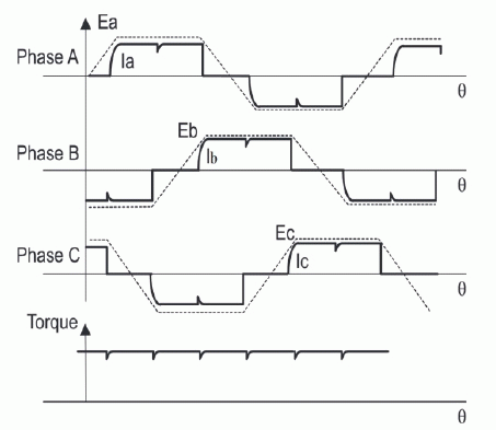
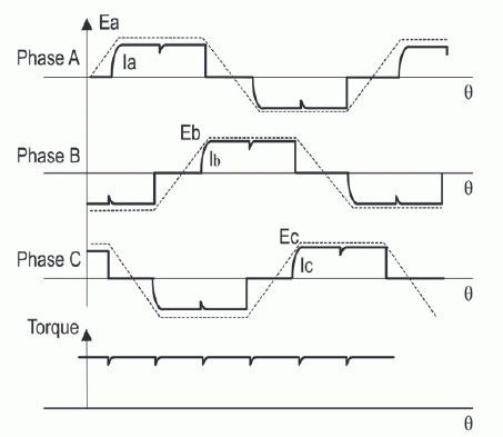
| Trapezoidal control is suitable for motors with Sinusoidal Back-EMF as the produced torque is not constant but made up from portions of a sine wave as shown in the figure 6. This is due to the application of a Trapezoidal Control strategy for a motor with sinusoidal Back-EMF. |
| The main advantage of this scheme is that it is relatively simple and cheap to implement since only one phase current needs to be controlled. Due to this, it is found to be ideal for low-cost applications which do not demand high performance. |
B. SINUSOIDAL CONTROL
|
| The principle of Sinusoidal Control is to drive all the three motor windings with three currents that vary smoothly and sinusoidally as the motor rotates. This requires modulation of the three winding currents such that the resulting space vector is always in the quadrature direction with respect to the rotor and has constant magnitude. |
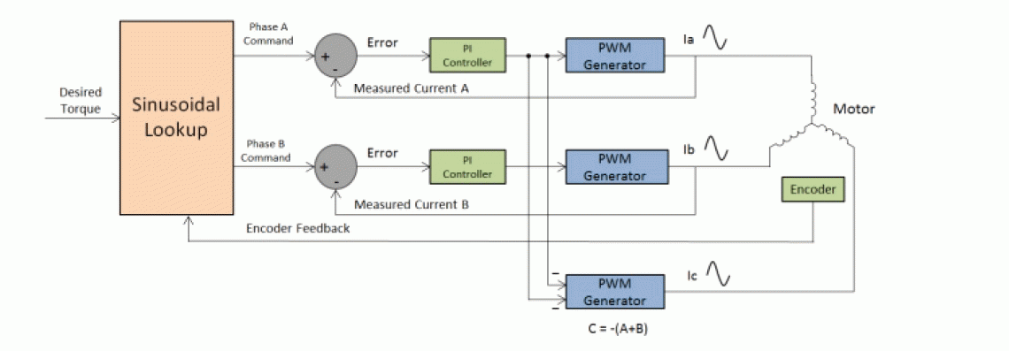
| In order to achieve this, accurate measurement of rotor position is required which can be provided by Resolver or Quadrature Pulse Encoders. Since the windings are star connected, the current in one of the windings is the negative sum of the currents in the other two windings. Hence, this scheme requires a current control loop for the first two windings. Figure 7 shows the typical block diagram of a sinusoidal control scheme. |
| The winding currents must combine to produce a smoothly rotating current space vector of constant magnitude, and because the stator windings are oriented 120o mechanically apart from each other, the currents in each winding must be sinusoidal and phase shifted by 120o. The position information from the encoder can be used to synthesize two sinusoids phase shifted 120o from each other by using a look-up table. These signals are then multiplied by a value so that the amplitudes of the sine waves are proportional to the desired torque. The result is two sinusoidal current command signals appropriately phased to produce the required rotating stator current space vector in the quadrature direction. These signals are then provided to a pair of PI controllers whose output is given to PWM generators. These PWM generators generate pulses to the Bridge circuits to control the voltage applied across the windings, which in turn controls the winding currents. Voltage applied to the third motor terminal is derived as the negative sum of the voltages applied to the first two windings. The resulting winding currents should track the reference sinusoidal current command signals in order to obtain a smoothly rotating current space vector, constant in magnitude and oriented in the quadrature direction. The extent to which the actual current tracks the reference signals depends on the implementation of the controllers as well. |
| Sinusoidal Control overcomes some of the drawbacks of Trapezoidal Control by eliminating Torque Ripple and offering smooth rotation with higher efficiency at low speeds. However, the PI controllers have limited gain and frequency response. As the speed increases, the frequency of the sinusoidal signals increase, making it more difficult for the controllers to track the reference current command signals. The lag and gain error in the current loops, which is inconsequential at low speeds, cause the current space vector to shift away from the desired quadrature direction producing unwanted torque in the direct axis direction. This leads to a reduction of useful torque by a given amount of current. The efficiency fades as more current is required to maintain the torque at the desired value. The speed can also only be increased up to a certain point, after which the phase shift in the current space vector exceeds 90o leading to negative torque. |
| The Sinusoidal Control scheme is used for both BLDC and PMSM motors in low speed-medium speed applications but unsuitable for operations that require high speed. |
C. FIELD ORIENTED CONTROL
|
| The Field Oriented Control algorithm shares lot of common ground with Sinusoidal Control. However, some fundamental differences allow it to achieve better efficiency at high speeds. The main drawback of Sinusoidal Control arises due to the fact that this control scheme tries to control the motor currents whose magnitude and direction varies with time. As the speed and frequency increase, the PI controllers are incapable of handling the operation due to their limited bandwidth. This problem can be overcome by representing and controlling the current space vector in the two axis d-q frame of reference. |
| This control scheme revolves around Clarke and Park Transformations, and their inverse. By applying these transformations, we can transform the 3Φ currents of the stator into the rotating frame of the rotor. |
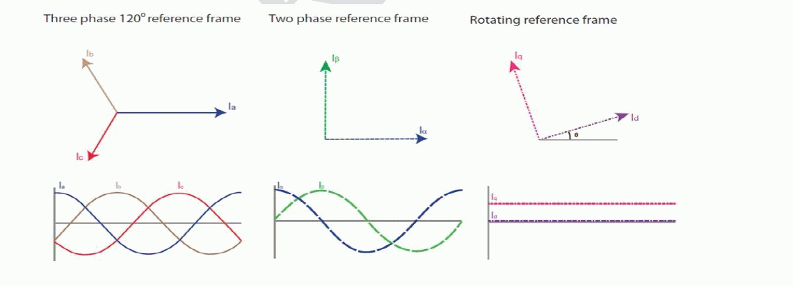
| By using Clarke Transformation, three-phase quantities are translated from the three-phase reference frame to the two-axis orthogonal stationary reference. However, the quantities are still in a stationary reference frame while the rotor reference frame is constantly rotating. Park’s Transformation converts these quantities into an orthogonal reference frame consisting of the direct and quadrature axis. The three reference frames are illustrated in figure 8. |
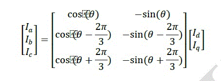
| The combined Clarke and Park Transformations can be written in Matrix form is as follows: |
 |
| Where θ is the angular position of the rotor. |
| Likewise, the inverse transformation is given by: |
 |
| As mentioned earlier in section I, the direct axis component produces useless torque while the quadrature axis component produces the torque responsible for rotation. In an ideal case, the current space vector in the d-q frame is fixed in magnitude and direction (quadrature) with respect to the rotor, irrespective of rotation. Since the current space vector in the d-q frame of reference is static, the PI controllers now have to operate on DC quantities rather than sinusoidal signals, thus greatly simplifying the control structure. This isolates the controllers from the time variant winding currents and voltages, and therefore eliminates the limitation of controller frequency response and phase shift on motor torque and speed. |
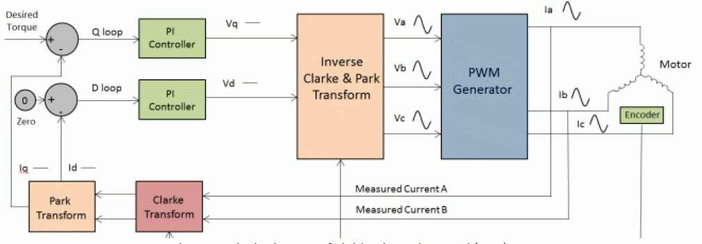
| The measured motor currents are first transformed from the three-phase static reference frame of the stator windings to the two axis rotating d-q reference frame, before being processed by the PI controllers. The voltages to be applied are then transferred back to the 3Φ reference frame and then sent to the PWM generator. The PWM generator generates the gating pulses for the arms of the bridge circuit of the drive to produce the required Voltage that is to be applied across the windings. |
| The block diagram for a standard FOC drive is shown in figure 9. The scheme uses two control loops, one for the direct axis current and the other for the quadrature axis current. Since our intention is to reduce the direct axis current, the reference input for the direct axis current is zero. The quadrature current loop takes the required torque as input. By driving the direct axis component to zero, the current space vector will be exclusively in the quadrature direction and the generated torque will track the reference torque input. |
| In sinusoidal control, commutation is performed first and is followed by PI control of the resulting sinusoidal current command signals. In Field Oriented Control, PI control of current is performed first and is followed by the commutation processes. By isolating the PI controllers from the time varying currents and voltages, the FOC algorithm is able to offer numerous advantages, such as: |
| • High Efficiency |
| • Smooth operation at low and high speeds resulting in a wide range of speed |
| • Transformation of a complex and coupled AC model into a simple linear system |
| • Fast dynamic response and good transient and steady state performance |
| The only limitation which was holding back the adoption of FOC was that the transformations that needed to be processed requires a lot of computation power and was difficult to implement as well. These days, microprocessors and DSPs with Vector Control features implemented into the Architecture itself are readily available in the market. This has led to a surge in the utilization of Brushless motors thanks to effective control strategies delivering high efficiency and meeting numerous requirements. |
| There are several techniques that can be used to implement pulse width modulation in FOC, the most notable ones being Sinusoidal PWM, Space Vector PWM and Third Harmonic Injection PWM. Soft Computing Techniques such as Fuzzy Logic, Genetic Algorithms, Neural Networks etc can also be used to implemented in applications which require the utmost accuracy [6]. |
COMPARISON OF SENSORS AND SENSORLESS TECHNIQUES
|
| All the control techniques mentioned above require the real time position information of the motor in order to function effectively. There are numerous ways to obtain the rotor position information, either by using sensors or by deducing the information through some other means. |
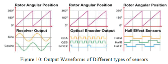
| The sensor-based techniques employ electromechanical sensors coupled to the rotor to provide the speed and position of the rotor. The most prevalent ones used today are Optical Encoders, Resolvers and Hall Effect sensors. Resolvers and Optical Encoders are externally mounted on the motor, while Hall sensors are mounted on the rotor itself. The sensor outputs for all the three types are shown in figure 10. |
| The resolver is the most accurate and also the most expensive among all the available sensors. It is essentially a rotary electrical transformer which generates analog signals that can be used to determine absolute position. Due to its high resolution, it is the preferred choice in industrial servo applications. |
| While not as precise as the Resolver, the Optical Encoders still offer fairly high resolution. It consists of an incremental rotating disk with a slot pattern on its periphery. A LED is mounted on one side of the disk and a phototransistor is mounted on the other side, opposite to the LED. The arrangement produces a set number of pulses for every 360o of rotation as shown in figure 10. |
| Hall Sensors are the most common sensors used in low-cost applications. Three hall-effect sensors are mounted on the rotor, which provides digital signals for every 60o of rotation of the rotor. |
| However, it is still possible to obtain the rotor position information without the use of position sensors. It not only lowers the overall complexity and cost of the setup but also eliminates delicate electronics which benefits applications with harsh working environments. |
| One way to obtain the motor speed and position is by measuring the Back-EMF [7]. The BEMF generated in the motor as it rotates is in the opposite direction of the energizing voltage according to Lenz’s law. The BEMF waveform varies as both a function of the rotor’s position and speed. This system reads the BEMF signals and looks for the zero-crossing points which occur when the BEMF voltage is equal to the motor’s neutral voltage. These zerocrossing points determine when to energize the windings. This technique can be employed in a wide range of motors and can work for either speed control or torque control. Back-EMF can also be estimated by measuring the currents flowing through the motor windings. |
| However, the detection of position using Back EMF is not possible at zero or low speeds. In other words, the motor is started in open loop. Hence, this method is only suitable for applications that do not require accurate closed loop operation at low speeds. |
| For low speed sensorless operation, the Induction Measurement technique is used. This method is based on the fact on the fact that the rotor position of a brushless motor has a slight effect on the electrical characteristics of the coils, even when it is not moving. This small affect can be measured, particularly for motors that have larger saliency, and the rotor position can be deduced from this measurement. |
CONCLUSION
|
| The control strategies detailed in this paper each have their own advantages and drawbacks. Trapezoidal Control is relatively simple and offers smooth operation at high speed but causes torque ripple at low speeds. Sinusoidal Control eliminates torque ripple and provides efficient operation at low speeds but the limitations of a PI controller make it unsuitable for high speed applications. Field Oriented Control (FOC) combines the best aspects of the previous two methods, offering smooth and efficient operation with fast dynamic response at both low and high speeds. The decision to implement sensors also depends on various factors. Excluding sensors will reduce the cost and size of the system but increase the complexity as rotor information needs to be deduced from other means. It is up to the designer to choose the most appropriate control technique that meets his requirements while minimizing the cost. |
Figures at a glance
|
 |
 |
 |
 |
 |
| Figure 1 |
Figure 2 |
Figure 3 |
Figure 4 |
Figure 5 |
 |
 |
 |
 |
 |
| Figure 6 |
Figure 7 |
Figure 8 |
Figure 9 |
Figure 10 |
|
| |
References
|
- R. Krishnan, Electric Motor Drives Modeling, Analysis and Control, Prentice Hall 2001.
- 2.Pragasen P, Ramu Krishnan, Application Characteristics of Permanent Magnet Synchronous and Brushless DC Motors for Servo Drives. IEEETransactions on Industry applications. Volume 27, No. 5, 1991: 986-996.
- S Wu, L Song, S Cui, Study on improving the performance of permanent magnet wheel motor for the electric vehicle application, IEEE Trans.Magn. 2007; 43(1): 438-442.
- 4.Bimal K. Bose, Modern Power Electronics and AC Drivers, Prentice Hall, 2002.
- 5.Pragasen P, Ramu K, Control Characteristics and Speed Controller Design for a High-Performance Permanent Magnet Synchronous Motor Drive,IEEE Transactions on Power Electronics. Volume 5, No .2,1991: 151-158.
- 6.A.Accetta, M.Cirrincione, M.Pucci, TLS EXIN based neural sensorless control of a high dynamic PMSM, Control Engineering Practice, vol.20,issue.7, pp.725-732, July 2012.
- Son, Y.-C, Bon-HoBae, Seung-Ki Sul, Sensorless operation of permanent magnet motor using direct voltage sensing circuit, 37th IAS AnnualMeeting. Conference on Industry Applications, 2002.
- T.S. Low, M.F. Rahman, Comparison of two Control Strategies in development if High-Torque Electronically Commutated Drive, IEEE Proceedings-B. Volume 139, No. 1, 1992: 26-36.
- P. Pillay and R. Krishnan., Modeling of permanent magnet motor drives, Industrial Electronics, IEEE Transactions on, Vol. 35, 537-541, 1988.
|