Keywords
|
| Fractals, shrinking size, antenna Wireless Communication |
INTRODUCTION
|
| In today world of wireless communications, there has been an increasing need for more compact and portable communications systems. Just as the size of circuitry has evolved to transceivers on a single chip, there is also a need to evolve antenna designs to minimize the size. Currently, many portable communications systems use a simple monopole with a matching circuit. However, if the monopole were very short compared to the wavelength, the radiation resistance decreases, the stored reactive energy increases, and the radiation efficiency would decrease. As a result, the matching circuitry can become quite complicated. As a solution to minimizing the antenna size while keeping high radiation efficiency, fractal antennas can be implemented. The fractal antenna not only has a large effective length, but the contours of its shape can generate a capacitance or inductance that can help to match the antenna to the circuit. Fractal antennas can take on various shapes and forms. For example, a quarter wavelength monopole can be transformed into a similarly shorter antenna by the Koch fractal. |
LITERATURE REVIEW
|
| Number of methods that can be used to reduce the size of the antenna when it is to be used at lower operating frequencies. Fractal is one of the ways which can be used to miniaturize antennas due to their space filling ability. It helps in fitting large electrical lengths into small volume .Mobile communications has become an important part of the life. Original applications such as mobile phones, GPS, Bluetooth technology have shown tremendous growth, and new applications such as, wireless local area network, wireless internet are emerging every day. Mobile means practical for user and easily transportable. Thus the mobile terminals for wireless application should be light, small, and should have low energy consumption to satisfy these requirements. Size of transceiver needed for the mobile applications have decreased drastically. Hence the size of the antenna should be compatible with the dimensions of the receiver .Several techniques for reducing the size of the patch have been presented in the past. Simplest is the use of substrate material with high dielectric constant [3] but it results in narrow bandwidth and poor efficiency due to surface wave excitation. Cost of low loss, high dielectric constant material is another problem. Other methods reported in the literature are shorting posts use of short circuits [4], and cutting slots in the radiating patch [4, 5]. The short circuit and shorting posts pose the problem of cross-polarization and partially filled permittivity substrate sometimes offers fabrication problem. Thus the high convoluted shape of a fractal allows to reduce the overall volume occupied by the resonating elements. |
FRACTALS
|
| The term fractal, which means broken or irregular fragments, was originally coined by Mandelbrot [to describe a family of complex shapes that possess an inherent self-similarity, self affinity in their geometrical structure. The original inspiration the development of fractal geometry came largely from an in-depth study of the patterns of nature. For instance. fractals have been successfully used to model such complex natural objects as galaxies, cloud boundaries, mountain ranges, coastlines, snowflakes, trees, leaves, ferns, and much more. Since the pioneering work of Mandelbrot and others. a wide variety of validations for fractals here has been an ever-growing demand, in both the military as well as the commercial sectors, for antenna designs that pos was originally coined by Mandelbrot to describe a family of complex shapes that possess an inherent self-similarity c,r self affinity in their geometrical structure. The original inspiration for Traditional approaches to the analysis and design of antenna systems have their foundation in Euclidean geometry. There has been a considerable amount of recent interest, however, io the possibility of developing new types of antennas that employ fractal rather than Euclidean geometric concepts in their design. We refer to this new and rapidly growing field of research as fractal antenna engineering. Because fractal geometry is an extension of classical geometry, its recent introduction provides engineers with the unprecedented opportunity to explore a virtually limitless number of previously unavailable configurations for possible use in the development of new and antenna designs. |
A. WHY FRACTALS?
|
| Advantages of fractal antenna technologies [2] |
| • Miniaturization of antenna size |
| • better input impedance matching wideband/multiband instead of many frequency independent ,reduced mutual coupling in fractal array |
| • Achieve resonance frequencies that are multiband. |
| • May be optimized for gain. |
| • Achieve wideband frequency band. |
| Some of these unique geometries. [6] |
KOCH CURVE
|
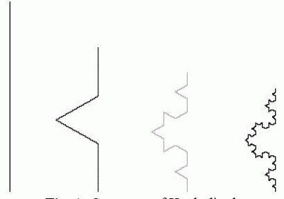
| The expected benefit of using a fractal as a dipole antenna is to miniaturize the total height of the antenna at resonance, where resonance means having no imaginary component in the input impedance. The geometry of how this antenna could be used as a dipole is shown in Fig 1. |
| A Koch curve is generated by replacing the middle third of each straight section with a bent section of wire that spans the original third. Each iteration adds length to the total curve which results in a total length that is 4/3 the original geometry. |
 |
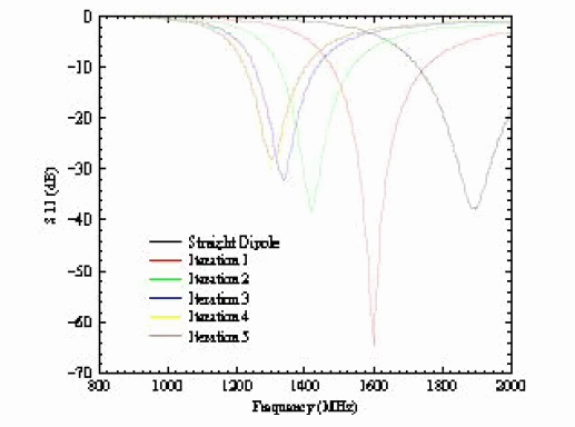
| The miniaturization of the fractal antenna is exhibited by scaling each iteration to be resonant at the same frequency. The miniaturization of the antennas shows a greater degree of effectiveness for the first several iterations. The amount of scaling that is required for each iteration diminishes as the number of iterations increase. The total length of the fractals at resonance is increasing, while the height reduction is reaching an asymptote. Therefore, it can be concluded that he increased complexity of the higher iterations are not advantageous. The miniaturization benefits are achieved in the first several iterations (Fig. 2). |
| Loop antennas are well understood and have been studied using a variety of Euclidean geometry. The have distinct limitations, however. Resonant loop antennas require a large amount of space and small loops have very low input resistance. A fractal island can be used as a loop antenna to overcome these drawbacks. |
| Fractals loops have the characteristic that the perimeter increases to infinity while maintaining the volume occupied. This increase in length decreases the required volume occupied for the antenna at resonance. For a small loop, this increase in length improves the input resistance. By raising the input resistance, they antenna can be more easily matched to a feeding transmission line. |
KOCH LOOP
|
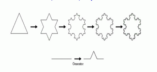
| The starting pattern for the Koch loop that is used as a fractal antenna is a triangle. From this starting pattern, every segment of the starting pattern is replaced by the generators. The first four iterations are shown in Fig. 4. The starting pattern is Euclidean and, therefore, the process of replacing the segment with the generator constitutes the first iteration. |
| The area of the fourth iteration of the fractal loop, which is a key parameter for small loop antennas, with radius R, is given by |
 |
| The area of a circle is given by |
 |
| Therefore, if the two areas are compared: |
 |
| It can be seen that the area of the fourth iteration of the Koch loop is 35% smaller than a circumscribed circle. The permiter of the fourth iteration of a Koch loop is given by |
 |
| The circumference of a circle is: |
 |
| Therefore, the perimeter of a fourth iteration Koch loop is 2.6 times longer than a circumscribed circular loop. |
 |
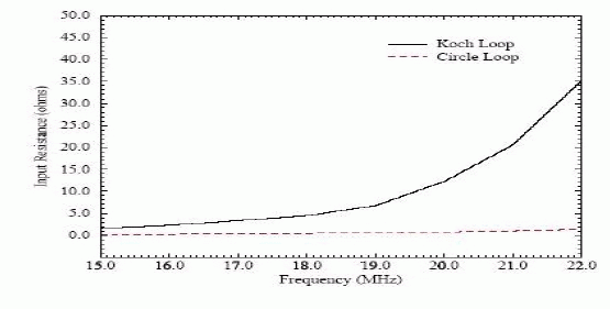
| Input resistances, with regarding to perimeter, are compared and shown in Fig. 5 |
MINKOWSKI LOOP
|
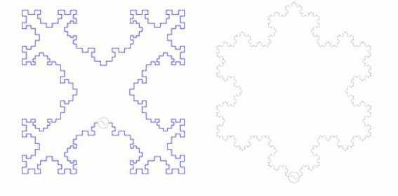
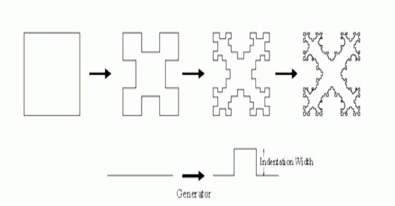
| Minkowski loop (Fig. 6) can be used to reduce the size of the antenna by increasing the efficiency with which it fills up its occupied volume with electrical length. A Minkowski fractal is analyzed, where the perimeter is near one wavelength. Several iterations are compared with a square loop antenna to illustrate the benefits of using fractal antennas |
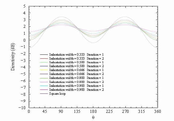
| Far field patterns for resonant fractal loop antennas for various indentation widths and fractal iterations as computed by the moment method. The pattern cut is orthogonal to the plane of the loop (Fig. 7). |
SIERPINSKI SIEVE
|
| So far, only the space saving benefits of fractal antennas have been exploited. There is another property of fractals that can be utilized in antenna construction. Fractals have self-similarity in their geometry, which is a feature where a section of the fractal appears the same regardless of how many times the section is zoomed in upon. Self-similarity in the geometry creates effective antennas of different scales. This can lead to multiband characteristic antennas, which is displayed when an antenna operates with a similar performance at various frequencies. The generation of the fractal is shown in Fig. 8. A Sierpinski sieve dipole can be easily compared to a bowtie dipole antenna, which is the generator to create the fractal. The middle third triangle is removed from the bowtie antenna, leaving three equally sized triangles, which are half the height of the original bowtie. The process of removing the middle third is then repeated on each of the new triangles. For an ideal fractal, this process goes on infinite no of times |
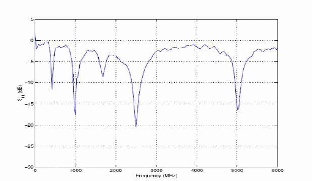
| The antennas were analyzed using the moment m (Fig. 9). |
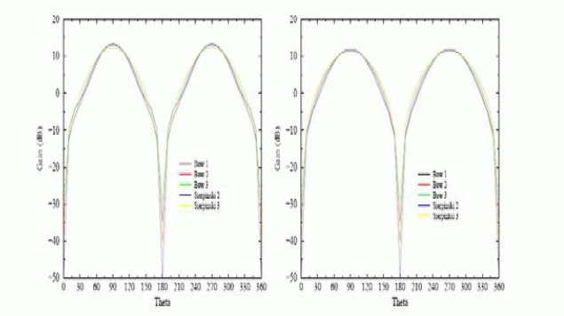
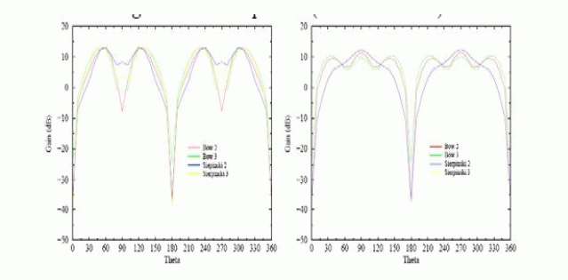
| These three resonances relate to the three sizes of the bowtie antennas and the three self-similar sizes inside the Sierpinski antennas. Each resonance is approximately twice that of the one before. This is what would be intuitively expected knowing that the self-similar features of the geometry are scaled by a two for each iteration. The benefits of the multiband behaviour can be seen in the far field pattern plots for these antennas. The far field patterns for the antennas at their first, second, and third resonance factor of are shown in Fig. 10, and Fig. 11 |
APPLICATIONS OF FRACTAL ANTENNAS
|
| There are many applications that can benefit from fractal antennas. Discussed below are several ideas where fractal antennas can make an real impact. The sudden growth in the wireless communication area has sprung a need for compact integrated antennas. The space saving abilities of fractals to efficiently fill a limited amount of space create distinct advantage of using integrated fractal antennas over Euclidean geometry. Examples of these types of application include personal hand-held wireless devices such as cell phones and other wireless mobile devices such as laptops on wireless LANs and networkable PDAs. Fractal antennas can also enrich applications that include multiband transmissions. This area has many possibilities ranging from dual-mode phones to devices integrating communication and location services such as GPS,the global positioning satellites. Fractal antennas also decrease the area of a resonant antenna, which could lower the radar cross-section (RCS). This benefit can be exploited in military applications where the RCS of the antenna is a very crucial parameter. |
LIMITATIONS
|
| Various limitations are as follows: |
| • Gain loss |
| • Complexity |
| • Numerical limitations |
| • The benefits begin to diminish after a few iterations |
CONCLUSION
|
| Many variations of fractal geometries have been incorporated into the design of antennas. Further work is required to get an understanding of the relationship between the performance of the antenna and the fractal dimension of the geometry that is utilized in its construction. This requires two courses of action. The first course of action requires that many more examples of fractal geometries are applied to antennas. The second crucial course of action is to attain a better understanding of the fractal dimension of the geometries such that correlations can be drawn about this dimension and the performance of the antenna. Also important is that the design of the antenna approaches an ideal fractal as much as possible. Several iterations can be studied to understand the trends that govern the antenna to better understand the physics of the problem |
Figures at a glance
|
 |
 |
 |
 |
| Figure 1 |
Figure 2 |
Figure 3 |
Figure 4 |
 |
 |
 |
 |
| Figure 5 |
Figure 6 |
Figure 7 |
Figure 8 |
 |
 |
 |
| Figure 9 |
Figure 10 |
Figure 11 |
|
| |
References
|
- P.Baliarda, J.Romeu, and A.Cardama, “The Koch monopole: A small fractal antenna”, IEEE Trans. Antennas and Pro November 2000 ewfractal antennas for compact and versatile telecommunication services”, Mvol. 43, pp. 196, January 2000
- Omeu and J.Soler, “Generalized SierpinskiFractalMultiband Antenna”, IEEE Trans. Antennas and Propagation 2001 .
- Gianvittorio, Y. Rahmat-Samii, “Fractal Antenovel antenna miniaturization technique, and applications”, IEEE Antennas and Propagation Magazine, vol. 44, February 2002
- Douglas Werner, Joshua Petko, Thomas Spence, “ Fractal Antennas”, Antenna Engineering Handbook .
- NemanjaPoprzen,MicoGacanovic“Antennas Fractal :Design ,Characteristics and Application”2003
- R. Garg, P. Bhartia, I. Bahl, and A. Ittipiboon, Microstrip Antenna Design Handbook, Artech House, 2000..
- D. R. Jackson, S. A. Long, J. T. Williams, and V. B. Davis,“Computer- a aided design of rectangular microstrip antennas”, c h.5 of Advances in Microstrip and Printed Antennas, K. F. Lee, Editor, John Wiley, 1997.
- D. M. Pozar, “A reciprocity method of analysis for printed slot and slot coupled Microstrip antennas,” IEEE Trans. Antennas and Propagation, vol.AP34
- S K Behera, “Novel Tuned Rectangular Patch Antenna As a Load for Phase Power Combining” Ph.D Thesis, Jadavpur University, Kolkata.
- Balanis, “Antenna Theory, Analysis and Design,” John Wiley & Sons, New York, 1997.
- Philip Felber. A literature study as a project for ECE 576.Illinois Institute of Technology. December 12, 2000
- Sarita Bajaj, Ajay Kaushik ,“International Journal of Engineering Research and Applications”,(IJERA) ISSN: 2248-9622 www.ijera.com Vol.2, Issue 1, Jan-Feb 2012, pp.229-23313.
- http://fracetenna.com T,FractalAntennaSystems
|