Keywords
|
| Fractal, Slot, Dielectric, Microstrip, DGS. |
INTRODUCTION
|
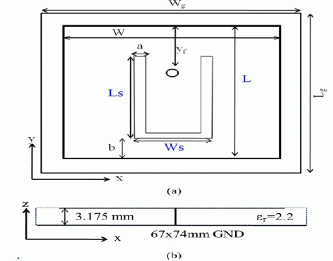
| In today world of wireless communication, recent developments in wireless communication industry continue to derive requirement of small, compatible and affordable microstrip patch antennas. A patch antenna is a narrowband, widebeam antenna fabricated by etching the antenna element pattern in metal trace bonded to an insulating dielectric substrate such as a printed circuit board with a continuous metal layer bonded to the opposite side of the substrate which forms a ground plane [4].The EM waves is produced by an antenna which is so called transducer because it transform electric current in to EM waves and by receiving vice versa [8]. Radiation of antenna by changing the current inside a conductor wire is the concept of radiations of antenna. By accelerating or decelerating the current in a straight wire, the current will create a flow which makes the antenna radiate, if current will not flow antenna never radiate [15]. Common microstrip antenna shapes are square, rectangular, circular and elliptical, but any continuous shape is possible. The resulting structure is less rugged but has a wider bandwidth because such antennas have a very low profile, are mechanically rugged and can be shaped to conform to the curving skin of a vehicle [8]. They are often mounted on the exterior of aircraft and spacecraft or are incorporated into mobile radio communications devices. Microstrip antennas are best choice for wireless devices because of characteristics like low profile, low weight, ease of fabrication and low cost. Since it is common practice to combine several radios into one wireless and use single antenna. Microstrip antenna suffers from disadvantages like they have less bandwidth and gain [16]. For obtaining multiband and wideband characteristics, different techniques have been used like cutting slot in patch, fractal geometry [2] and DGS [10]. In order to increase bandwidth DGS has been used. DGS may be realized by cutting shape from ground plane. Shape can be simple or complex. When DGS has been applied to antenna equivalent inductive part due to DGS increases and this cause high effective dielectric constant hence bandwidth reduced. It is to be noted that within particular area of ground different DGS can produce different resonant frequencies and different bandwidth. In this paper two radiating u slot in ground plane have been cut out. Hence new resonances along with effective current paths are generated in ground plane, as result wideband characteristics have been obtained [5]. |
LITERATURE SURVEY
|
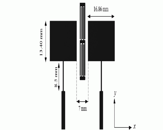
| Alsath et al.[1] proposed approach to enhance isolation in microstrip patch antenna arrays is described. A Defect is introduced called as meander line resonator by creating defect known as band notch function. Resonator is designed to block surface current at resonant frequency of two patch antenna. This antenna provided an improvement in isolation by 16 dB with reduced edge to edge spacing of 7 mm. This design and simulation has been carried out using antenna simulation software. The resonator is designed to block the surface current at the resonant frequency of the two patch antennas coupled along H-plane and operating at a frequency of 4.8 GHz. The interelement isolation before and after the implementation of SMLR has been investigated. |
| Khidrewt al.[2] proposed dual beam microstrip antenna, Two radiation beams were obtained by operating patch at higher order mode instead of fundamental mode. In this, bandwidth of antenna is obtained by making use of u shaped patch. Conventional U slot patch antenna, parametric analysis is analyzed. Also effect of U slot inclusion on performance of patch antenna was analyzed. Antenna was designed and simulated using HFSS simulated software and good effects were obtained between practical and experimental results. The antenna operating frequency range is 5.18– 5.8 GHz with VSWR less than 2, which corresponds to 11.8% impedance bandwidth. It exhibits two radiation beams, directed at 35 and with 7.92 dBi and 5.94 dBi realized gain, respectively at 5.5 GHz |
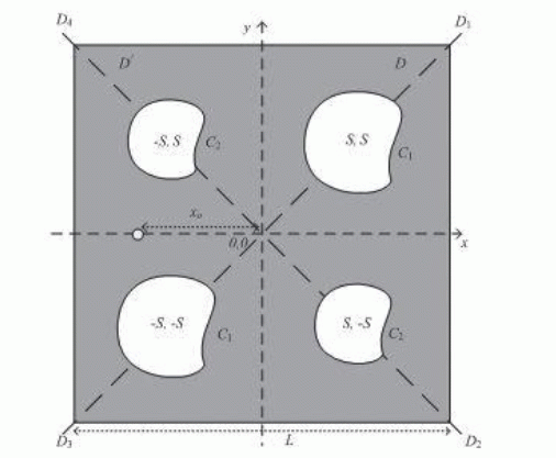
| Nasimudin et al. [3] proposed circular symmetric slotted microstrip patch antenna with compact size. This antenna was obtained by cutting shapes in diagonal directions of microstrip patch antenna. . A measured 3 dB axial-ratio (AR) bandwidth of around 0.7% (6.0 MHz) with 2.0% (18.0 MHz) impedance bandwidth was achieved. The measured boresight gain was more than 3.3 dBi over the operating band was obtained. Different shapes for the slots are studied and compared, based on the fixed overall volume of the antenna for circularly polarized diagonally symmetric slotted microstrip-patch antennas. This antenna was designed to have compact size of small dimensions. |
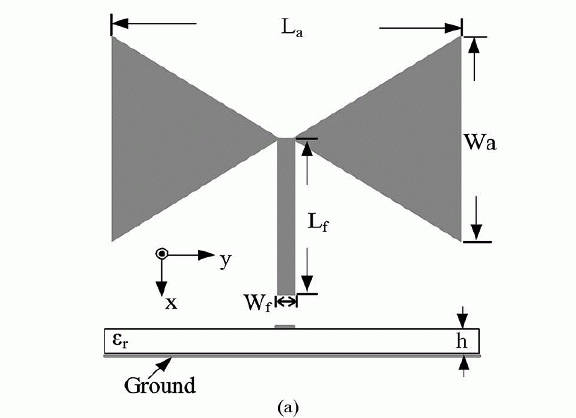
| Liu et al. [4] proposed triband bowtie antenna using slot technique. This antenna was obtained by inserting two pairs of slot with different length of isosceles triangle without increasing area of triangle. This antenna is designed to operate for three different bands applications. Antenna was resonated at three different bands but its dimensions were made for middle frequency band. This antenna was resonated for 3.5 GHz, 4.5 GHz and 5.8 GHz. Design and simulation was carried out using antenna simulation software. |
| Moosazadeh et al. [5] proposed small and compact triple band microstrip fed printed monopole antenna for wireless local area network. This antenna was used for Wireless Local area network applications and Wi-Max application. The proposed antenna consists of a rectangular radiating patch with L- and U-shaped slots and ground plane. A parametric study on the lengths of the U- and L-shaped slots of the proposed antenna was provided to obtained the required operational frequency bands—namely, WLAN(2.4/5.2/5.8 GHz) and WiMAX (2.5/3.5/5.5 GHz). The proposed antenna was small (15 15 1.6 mm ) when compared to previously well-known double- and triple-band monopole antennas. |
ANTENNA DESIGN
|
| In this paper The steps [16] to obtain the dimensions are as follows |
| Step 1: Determination of the Width (W) |
| The width of the microstrip patch antenna is given by (1) |
 (1) (1) |
| Step 2: Calculation of effective dielectric constant, εreff , which is given by equation (2) |
 (2) (2) |
| Step 3: Calculation of the length extension ΔL, which is given by (3) |
 (3) (3) |
| Step 4: Now to calculate the length of patch by (4) |
 (4) (4) |
| Where the effective length of the patch Leff |
 (5) (5) |
| Step 5: Calculation of Ground Dimensions |
| |
| Lg=6h+L (6) |
| Wg=6h+W (7) |
| In this paper after review and studying dimensions of patch are taken same with respect to reference paper [1] and work has been carried out to modify the patch structure to obtain improved results in respect to return loss and bandwidth at same frequency. |
INITIATOR PATCH DESIGN
|
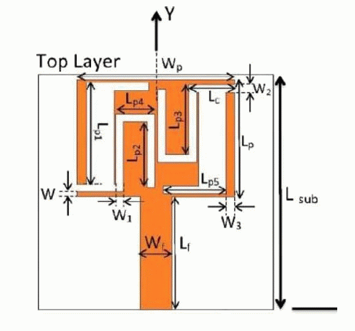
| Microstrip antenna has been used for various applications like defense, airplane and military applications. But these antenna suffers from disadvantages of small bandwidth, gain and return loss. In order to improve antenna characteristics, different techniques have been used like use of fractal geometry, defected ground structure and slot cutting slot. In this dissertation, slots have been cut on side of patch so as to obtain better characteristics; initially patch of length 30 mm is taken and analyzed using coaxial feed at (1, 13, 0). FR-4 has been used as substrate with dielectric constant of 4.4 and loss tangent of 0.02. Design is modified by making a u slot so as to make similar to that of reference antenna as there are certain draw backs of microstrip antenna. |
CONCLUSION
|
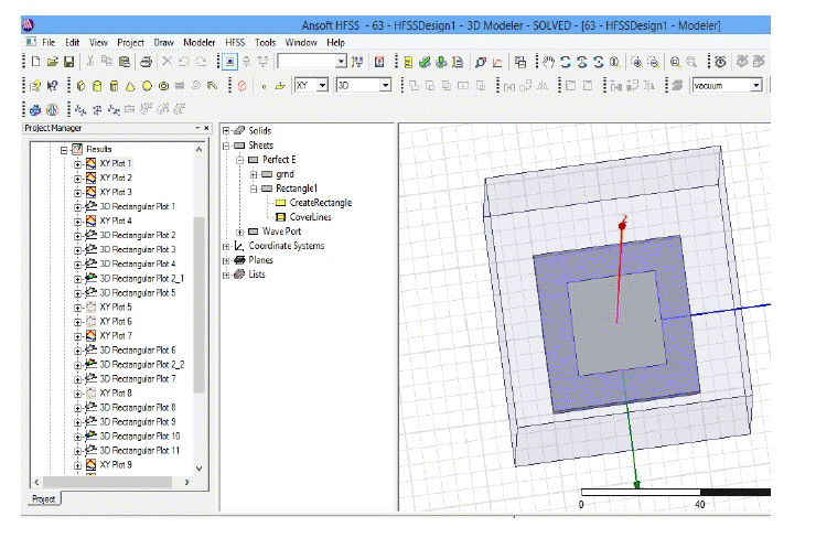
| This paper shows the review and survey of techniques and design for the designing of efficient microstrip patch antenna. By using one of any above mentioned technique some of the limitations of conventional microstrip characteristics is improved. This review work is done on some characteristics implemented through different techniques. Nevertheless, useful solution are still less and suffer from different problems like complexity of structure ,reduced bandwidth, reduction of gain etc. Hence, the author feels that further research and more work is needed in these areas. After searched the gap of research paper, reached at the point where is the a design has been discussed in this paper based on HIGH FREQUENCY STRUCTURE SIMULATOR. In this design all the techniques will be used for analysis the parameters OF ANTENNA. |
Tables at a glance
|
 |
 |
| Table 1 |
Table 2 |
|
| |
Figures at a glance
|
 |
 |
 |
| Figure 1 |
Figure 2 |
Figure 3 |
 |
 |
 |
| Figure 4 |
Figure 5 |
Figure 6 |
|
| |
References
|
- M.Gulam, S. Malathi 2014, âÃâ¬Ãâ¢Implementation of Slotted Meander-Line Resonators for Isolation Enhancement in Microstrip Patch AntennaArrays âÃâ¬Ãâ, IEEE Transactions on Antennas and Propagation.
- Kidre A., 2014 âÃâ¬Ãâ¢Wide band dual beam U- slot Microstrip antenna”, IEEE transaction of Antennas And Wireless Propagation Letters, Vol. 61pp 1415-19.
- Nasimuddin, 2014, âÃâ¬Ãâ¢Slotted microstrip antennas for circular polarization with compact sizeâÃâ¬Ãâ, IEEE Antenna And Wireless Propagation Letter,Vol. 55, pp 127-34.
- Liu H., 2014, âÃâ¬Ãâ¢Single feed slotted bowtie antenna for triband applicationâÃâ¬Ãâ, IEEE Antenna And Wireless Propagation Letter, Vol. 12, pp 1658-61.
- Moosazadeh 2014 “Compact & small planar monopole antenna with symmetrical L- &U- shaped slots for WLAN/WiMAX ApplicationsâÃâ¬Ãâ IEEE Antenna And Wireless Propagation Letter, Vol. 13, pp 388-91.
- MizamohammadiFarnaz, NouriniaJavad and GhobadiChangiz 2012 âÃâ¬Ãâ¢A Novel Dual-Wide Band Monopole- Like Microstrip antenna withcontrollable Frequency ResponseâÃâ¬Ãâ IEEE Antenna And Wireless Propagation Letter, Vol. 11, 2012.
- Ismail M.Y., Inam M., Zain A.F.M., Mughal MA. 2010 âÃâ¬Ãâ¢Phase and Bandwidth enhancement of Reconfigurable Reflect Array Antenna withslots Embeded PatchâÃâ¬Ãâ IEEE Antenna And Wireless Propagation Letter, Vol. 7, 2010.
- Yang Steven, Kishk A. Ahmad and lee Fong kai.âÃâ¬Ãâ¢Frequency Reconfigurable U-slot Microstrip Patch AntennaâÃâ¬Ãâ IEEE ANTENNAS AND WIRELESS PROPAGATION LETTERS, Vol.7, pp 127-129.
- Nagarajan V. , Chita R. Jothi âÃâ¬Ãâ¢Double L-Slot Microstrip Patch Antenna for WIMAX and WLAN applicationsâÃâ¬Ãâ Department of Electronics andCommunication Engineering, Adhiparasakhi Engineering College, Chennai, India.
- Wen Lengl, Aan-guo Wang, Xio-tao CAI âÃâ¬Ãâ¢Novel Radiation Pattern Reconfigurable Antenna with six beam choicesâÃâ¬Ãâ Science- Direct.com/Journals,April 2012 pp no-123-28.
- Liu Wen-Chung, Wu Chao-Ming and Dai Yang, 2011. âÃâ¬Ãâ¢Design of Triple-Frequency Microstrip-Fed Monopole Antenna Using DefectedGround StructureâÃâ¬Ãâ, IEEE Transaction on Antennas and Propagation, Vol.10, pp 2457-2463..
- Jung won Chang, Ha Sangjun âÃâ¬Ãâ¢Single Beem Steering Antenna With U-SlotâÃâ¬Ãâ@ 2011 crown. Chen Wen-Ling, Wang Guang-Ming, and ZhangChen- Xin, 2009. âÃâ¬Ãâ¢Bandwidth Enhancement of a Microstrip-Line-Fed Printed Wide-Slot Antenna With a Fractal-Shaped SlotâÃâ¬Ãâ, IEEETransaction on Antennas and Propagation, Vol.59, No.7, pp 2176-2179.
- Golpour M., Koohestani m. âÃâ¬Ãâ¢U-shaped microstrip Patch Antenna with parasitic tunning stubs for Ultra Wide Band ApplicationsâÃâ¬Ãâ Published inIET Microwave, Antennas &Propgation. Revised on 15th Feb 2009.
- BaikSeung-hun Park Jongkuk, Na Hyung-gi âÃâ¬Ãâ¢Design of L-probe Microstrip Patch AntennaâÃâ¬Ãâ IEEE ANTENNA AND WIRELESS PROPAGATION LETTERS, VOL. 3, 2004pp no 117-120.
- Kim S.Y., kim M., Sung J. Y.âÃâ¬ÃâHarmonics Reduction With Defected Ground Structure for a Microstrip Patch AntennaâÃâ¬Ãâ IEEE ANTENNA AND WIRELESS PROPAGATION LETTERS VOL. 2,2003 pp no 111-112
- Balanis a. Constatine âÃâ¬Ãâ¢ANTENNA THEORY AND ANALYSIS DESIGNâÃâ¬Ãâ a john willey& sons, inc. publication.
|