Keywords
|
| Boost converter, PCC algorithm Fuzzy controller, Steady state error, predictive peak current control, sensorless. |
INTRODUCTION
|
| In recent years, predictive current control (PCC) is a digital controlled DC-DC converters in continuous current mode (CCM) and it is a control mechanism. Therefore, it has been extensively studied by many researchers investigated a high performance PCC based on dead-beat control strategy, which shows a great advantage of low calculation complexity. However, the response is quite slow due to its current error elimination once every four switching cycles. A fast response PCC strategy is proposed by [2], whereby the disturbance of the inductance current can be eliminated in two switching cycles, whether in the valley, peak or average current control modes. Many PCC strategies have been proposed recently, but all the Strategies need to sample the inductor current using a current sensor. In current control mode, the compensation circuit slope is necessary to maintain system stability, when the pulse width modulation (PWM) duty ratio is higher than 50% [9]. In PCC mode, the next switching of the duty ratio can be calculated and next switching cycle of the inductor current can be predicted according to the reference current and predicted current. The precise current sampling is necessary for PCC of a boost converter system. The current sampling three types are shunt resistor, current mirror, and the last one is Hall current sensor. The last one is the most accurate, but the Hall current sensors cost is relatively high, and it reduces system reliability. The sensorless current control should be estimated current by using current observer. The Fuzzy logic controller can be used in sensorless current control. The input voltage of the system is 12V and the output voltage is boosted 48V by using boost converter. The fuzzy controller should be used get a stable output voltage. The pulse width modulation technique would be used. This technique can be used to give a pulse signal to drive circuit. |
| The aim of this research is mainly to eliminate the output voltage steady state error without using current sensor. The main objectives of this research can be summarized as: |
| 1. To design and implement battery charger application, which are simple, reliable, low cost and high efficiency. |
| 2. To predictive peak current control mode using Fuzzy controller. |
BLOCK DIAGRAM
|
| DC source is given to boost inductor to boost the voltage and the boosted voltage is filtered using filter. The input voltage and output voltage feedback is calculated using current calculation block and it is compared with the reference value which we set already. After that the output is given to fuzzy controller. This fuzzy controller is used to control the Gate driver circuit for driving the switches. This process is continued up to getting the correct peak current value. The input voltage of the converter is 12V and get the output voltage is 48V by using boost converter. It consists of the following sections are DC-DC converter, Fuzzy controller, and PWM driver circuit.The Proposed block diagram as shown in figure 1. |
A. Boost converter
|
| A Boost Converter (step-up converter) is a power converter with an output DC voltage greater than its input DC voltage. It is a class of Switching-mode power supply (SMPS) containing at least two semiconductor switches (a diode and a transistor) and at least one energy storage element. Filters made of capacitors (sometimes in combination with inductors) are normally added to the output of the converter to reduce output voltage ripple. |
B. Fuzzy controller
|
| It can be controlled one or more than one inputs and outputs are controlled. It can be implemented in both linear and non-linear system.Fuzzy Logic provides a more efficient and resourceful way to solve Control Systems.Fuzzy logic provides an alternative way to represent linguistic and subjective attributes of the real world in computing.It is able to be applied to control systems and other applications in order to improve the efficiency and simplicity of the design process. This controller must be used in more membership function. Here, mamdani Fuzzy interference system (FIS) shown in figure 2. |
C. PWM gate driver circuit
|
| Pulse width modulator controller(SG355A) |
| PWM is used in all sorts of power control and converter circuits. Some common examples include motor control, DCDC converters, DC-AC inverters and lamp dimmers. There are numerous PWM controllers available that make the use and application of PWM quite easy. One of the most popular of such controllers is the versatile and ubiquitous SG3525, whose package is shown in the figure 3. |
| SG3525 is used extensively in DC-DC converters, DC-AC inverters, home UPS systems, solar inverters, power supplies, battery chargers and numerous other applications and its block diagram is shown in figure 4. |
SENSORLESS PEAK CURRENT CONTROL
|
| For PCC controllers with the basic current observer, the observed current will diverge due to the forward voltage of the diode and the parasitic resistors in the converter. More importantly, the divergence further induces steady state errors in the output voltage. The difference leads to the need for different mathematical modelling and controller optimization methods. By employing compensations for both the observed current and the sampled voltage, the CO-based PCC controller converges the observed current to the valley value of the inductor current, and eliminates the steady state error of the output voltage. The boost DC-DC converter with the current observer based PCC controller shown in figure 5. The input and output voltages are deduced inductor current and PWM duty cycle. It consists of two control loops. |
| The outer loop can be used Fuzzy control to control the voltage control loop. The inner loop used sensorless predictive current control mode to control the current control loop. Working in continuous current mode (CCM), without consideration of the parasitic parameters of inductor L and output capacitor C, using average inductor current Where D is the duty ratio, R is the equivalent load, and VIN(t) is the input voltage. Equations (1) and (2) are the basic boost converter state equations from which the observer can be derived. |
 (1) (1) |
 (2) (2) |
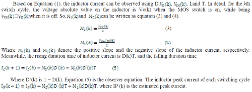 |
A. Peak current control mode
|
Figure 6 I REF is the reference current output from the PI regulator. There exists a deviation between IL(k) and I REF The PCC controller detects the current error, and adjusts the duty ratio, so that IL(k+2) reaches IREF. In this way, the current error can be eliminated in two switching cycles. As the switching cycle T is much shorter than the regulation time, the inductor current slope can be regarded as constant in two adjacent switching cycles. As shown above, the PCC controller can eliminate the current error in less than two switching cycles, which is relatively fast, so the converter can be designed with fast transient response. However, the CO-based PCC controller has problems such as the divergence of the observed current and the steady state error of the output voltage. An optimal current  |
| From (5), the PWM duty ratio of the k + 1th cycle is |
 (8) (8) |
| Using this equation together with (6) and (7) and substituting them into (8), the following equation can be deduced: |
 (9) (9) |
| which indicates that D(k + 1) is proportional to the difference between reference current and estimated current of the kth cycle. |
OUTPUT VOLTAGE STEADY STATE ERROR
|
| For the PCC controller with the basic CO, the observed current will diverge due to the diode forward voltage and the parasitic resistors in the converter. The divergence of the observed current degrades the reliability of the converter, and will cause the steady state errors in the output voltage. In the following section, the relationship among the parasitic parameters, the convergence of the observed current and the steady state error of the output voltage will be studied in detail. For a current-mode-controlled boost converter with a current sensor, the voltage loop FUZZY controller is able to eliminate ΔVo, which is the steady-state error of the output voltage, by providing a pole at the origin. When there is no pole at the origin in the open-loop transfer function, the integration effect of the FUZZY controller is nullified, and hence, the output voltage may have a steady-state error. |
| B. Calculation of ΔV0 |
| The actual inductor peak current Ip can be varied between the two neigh boring switching cycles is zero. This equation can be described as |
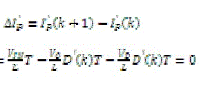 (10) (10) |
| Based on equation (5), the variation of Ip is |
 (11) (11) |
| From (10), the equation (11) can be obtained. |
 (12) (12) |
| If ΔV0=VSAMPLE-VREF, the negative ΔV0 leads the reference current to increase at a constant slope. According to the transfer function of the Fuzzy controller, the variation of IREF in the two neigh boring switching cycles is |
 (13) (13) |
| When the estimated inductor current compared with the actual inductor current it has two switching cycle delays because of the digital control character. If the steady state, ΔIREF= ΔIp,ΔV0 can be obtained from (12) and (13) as |
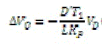 (14) (14) |
| According to (12) and (14) ΔIp and ΔV0, are proportional to V0. The input voltage is 12V and the output voltage is 48V. The main inductor current is 1mH. The current loop algorithm is based on (8), whereas the voltage loop is the Fuzzy controller. |
C. Current observer
|
| The observed current can be used to eliminate the steady state error of the output voltage. The current observer can be induces steady state error output voltage. The current observer strategy is proposed. This strategy can be observed the inductor current and then eliminate the steady state error of the output voltage. The digital system block diagram of the proposed controller figure 7 [6]. |
RESULT AND DISCUSSION
|
| In this paper represents the input voltage is 12V and get the boosted output voltage is 48V by using boost converter. Here, fuzzy controller is used to get the stable output voltage. In existing system PI controller is used but that controller cannot effectively eliminate the steady state output voltage error. So, here Fuzzy controller is used. It can be effectively eliminate the output voltage steady state error. Then controllers give the stable output voltage. |
| The output voltage and output current waveform as shown in figure 8.when the gate pulse is given to the MOSFET it will be generated the Pulse width modulation (PWM). The output voltage and current waveform as shown in figure 8. The Expanded part of voltage waveform is shown in figure 9. |
CONCLUSION
|
| A sensorless predictive peak current control with computing technique has been presented in this paper. The Fuzzy controller can be implemented in this paper. This controller can be effectively eliminate the voltage steady state error and achieve high accuracy current estimation without using current sensor.Byemploying the optimal current observer-based predictive current controller, a boost converter is implemented. The input voltage of the system is 12V and get the output voltage is 48V. The output of the system is stable. |
Figures at a glance
|
 |
 |
 |
 |
 |
| Figure 1 |
Figure 2 |
Figure 3 |
Figure 4 |
Figure 5 |
 |
 |
 |
 |
| Figure 6 |
Figure 7 |
Figure 8 |
Figure 9 |
|
| |
References
|
- Y. Li, K. R. Vannorsdel, A. J. Zirger, M. Norris, and D. Maksimovic, “Current mode control for boost converters with constant powerloads,”IEEE Trans. Circuits Syst. I, Reg. Papers, vol. 59, no. 1, pp. 198–206, Jan. 2012.
- M. Veerachary and R. Saxena, “Design of robust digital stabilizing controller for fourth-order boost DC–DC converter: A quantitative feedbacktheory approach,” IEEE Trans. Ind. Electron., vol. 59, no. 2, pp. 952–963,Feb. 2012.
- F. Taeed, Z. Salam, and M. Ayob, “FPGA implementation of a single input fuzzy logic controller for boost converter with the absence of anexternal analog-to-digital converter,” IEEE Trans. Ind. Electron., vol. 59,no. 2, pp. 1208–1217, Feb. 2012.
- Muruganandam, M. and Madheswaran, M. “Stability Analysis and Implementation of Chopper fed DC Series Motor with Hybrid PID-ANNController” Published in International Journal of Control, Automation and Systems, Springer, Volume 11, Issue 5, October 2013. ISSN: 1598-6446 (Print) 2005-4092 (Online)
- M. Muruganandam, M. Madheswaran, “Experimental verification of chopper fed DC series motor with ANN controller” Published inInternational Journal of Frontiers of Electrical and Electronic Engineering in China, (Springer Publication) Volume 7, Issue 4, December 2012,pp 477-489. ISSN: 2095-2732 (print) 1673-3584 (Online)
- M.Madheswaran and M.Muruganandam, “Simulation and Implementation of PID-ANN Controller for Chopper Fed Embedded PMDC Motor”Published in ICTACT Journal On Soft Computing, Volume 2, Issue 3, April 2012 pp 319-324. ISSN: 2229-6956(Online)
- Qiao Zhang, Run Min, Qiaoling Tong, XuechengZou, “Sensorless Predictive Current Controlled DC–DC Converter with a Self-CorrectionDifferential Current Observer,” IEEE Trans. Ind. Electron., VOL. 61, NO. 12, Dec 2014.
- C Nagarajan, M Muruganandam, D Ramasubramanian, “Analysis and Design of CLL Resonant Converter for Solar Panel-battery Systems”,International Journal of Intelligent Systems and Applications (IJISA), Volume 1, December 2012 pp 52-58.
- C.Nagarajan and M.Madheswaran – ‘Analysis and Implementation of LLC-T Series Parallel Resonant Converter with Fuzzy controller’- International Journal of Engineering Science and Technology (IJEST), Applied Power Electronics and Intelligent Motion Control. Vol.2 (10),pp 35-43, December 2010
- YingQiu, Helen Liu,andXiyou Chen, “Digital Average Current-Mode Control of PWM DC–DC Converters without Current Sensors,” IEEETrans. Ind. Electron.,VOL. 57, NO. 5, MAY 2010.
- Y. P. Hsieh, J. F. Chen, T. J. Liang, and L. S. Yang, “Novel high step-up DC–DC converter for distributed generation system,” IEEE Trans.Ind.Electron., vol. 60, no. 4, pp. 1473–1482, Apr. 2013.
- Muruganandam, M, Thangaraju I and Madheswaran, M. “Simulation and Implementation of an Embedded Hybrid Fuzzy Trained ArtificialNeural Network Controller for Different DC Motor” Published in International Journal of Engineering and Technology, Vol. 6, Issue 1, pp.315-332 February 2014. ISSN:0975-4024 (Online)
- C.Nagarajan and M.Madheswaran - ‘Performance Estimation of LCL-T Resonant Converter with Fuzzy / PID Controller’- International Journalof Computer and Electronic Engineering (IJCEE), Vol.2 (3), pp.534-542, June 2010
- C.Nagarajan and M.Madheswaran, “Analysis and Simulation of LCL Series Resonant Full Bridge Converter Using PWM Technique with LoadIndependent Operation” has been presented in ICTES’08, a IEEE / IET International Conference organized by M.G.R. University,Chennai.Vol.no.1, pp.199-207, Dec.2007.
- Mr.S.Saranraj, Mrs.A.Sasipriya, S.Ramkumar, M.Muruganandam “Voltage Controlled PFC SEPIC Converter Based PMBLDCM Drive for Air-Conditioners UsingFuzzy Controller” JAIR Vol.3, Issue 11, ISSN: 2278-7844, Nov 2014
|