Keywords
|
| MPPT, Partial shading, Adaptive LMS algorithm |
INTRODUCTION
|
| The energy needs of the world are currently in a crucial situation. Increasing number of population, industrial development, vehicle usage, urbanization will leads globe to face the energy scarcity in near future. Now we are maintaining the situation by means of conventional sources such as petroleum, coal, natural gases, but these resources are no longer available after fifty or hundred years. Also the conventional energy resources will badly affect the environment. The current trends in the development concept are sustainable development. This will leads to the need of usage of nonconventional energy resources such as solar power, wind power, and atomic power generation methods. The atomic power generation also recently shows that it is not perfectly secure in the natural calamities as seen in Fukushima Atomic Plant in Japan and also it is having major environmental problems in dumping the waste from atomic plants. Recently we have seen agitations against the atomic power plants in India, Japan and many other countries. So we are in search with more abundant, eco friendly, green energy resources such as solar and wind power. Although it is having this much of advantageous the technology is still in its teen-age. The maximum efficiency of the solar panel can be up to forty percentages only. More research is going on in the area of solar panel with better efficiency. Even also from the produced power we cannot effectively use the maximum power due to the losses the in the electronic parts used in the in solar systems |
| In our project aims to develop a electronic controlled solar energy harvesting system that can perform with better efficiency and can deliver maximum power to the load which is produced from the solar panel. The one method we can adopt is maximum power point tracking. The maximum power point is the point in the V-P characteristics of the solar array that can deliver maximum power. One factor that affecting the solar array efficiency is variations in the atmospheric condition will abruptly change the irradiation patterns in the solar cells. The other factors are temperature and the shading effects [2]. Due to these changes the power generated is changes and this will leads to impedance mismatching of source and the load. Thus according to the maximum power transfer theorem we cannot achieve the maximum power which is produced. In this situation there should be some interface logic that can vary its impedance according to the situation to deliver maximum power. A DC-DC converter can be used for this purpose. That can be a buck, boost or buckboost converter. Its resistance can be changed by using the duty cycle given to the converter. The duty cycle can be determined and controlled by an algorithm. Generally the algorithm that are used in this purpose are Perturb and Observe algorithm[7], Incremental conductance algorithm[6] etc,.In this method it will find the MPP by comparing current instant power with the previous instant one and accordingly increase or decrease its duty cycle of the PWM pulse. This will lead to updating in the voltage and reach to the MPP point. The disadvantages of this algorithms will be stuck on local maximum power points, slow response to sudden changes in irradiations, unwanted noises in the output and it is only concentrated in supply side irregularities. |
| In this paper proposes a new adaptive algorithm to track the Maximum PowerPoint at its varying conditions. Section (II) will describe the characteristics of the PV modules, section (III)will describe partial shading problem, Section (IV) will describe the proposed algorithm, Section (V) will contain the simulation results and conclusion. |
PV MODULE CHARACTERISTICS
|
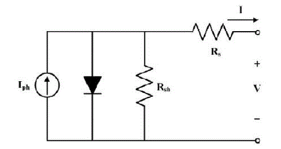
| Fig. 1 shows the typical equivalent circuit for PV arrays[1]. In general, the series parasitic resistance Rsis very small and the parallel parasitic resistance Rshis very large; they are negligible. To simplify the analysis from uncertain parameters, |
| Proposed equations with one uncertain parameter A following:[1] |
| Equations |
 (1) (1) |
| And |
 (2) (2) |
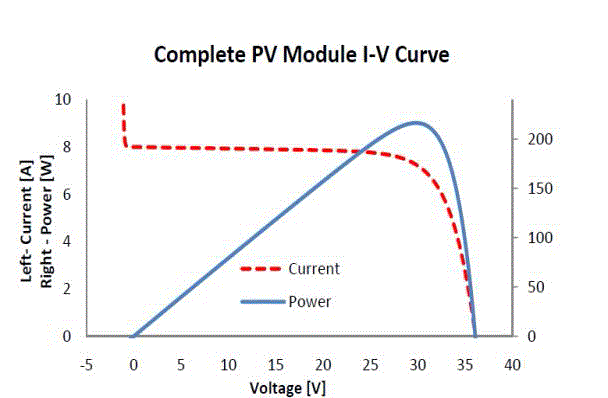
| V and I are the array output voltage and current respectively and L is the irradiance in kW/m2, and T is the temperature on the array in °C. VOC and ISC are the open-circuit voltage and the short-circuit current respectively at 1kW/m2 and 25°C. qis the Elementary charge and k is the Boltzmann’s constant. A is selected to 0.2464, and it showed great similarity compared to characteristics of an actual PV array. Fig. 2 shows the characteristics of a single PV panel current voltage and power-voltage characteristics respectively. The PV panel is considered: VOC = 35V and ISC = 8A at 1kW/m2 and 25°C.During the simulation process we simulate the model more accurately .The simulation model is very efficient in creating all the conditions that may affect the PV cell output[13]. |
PROBLEMS IN HARVESTING THE MAXIMUM POWER
|
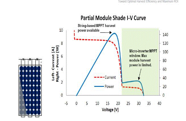
| In the series connected cell in the PV array, one cell gets shaded will offers infinite resistance, so it will reduce the output. So all the voltage will be dropped across that cell will produce heat in that cell and damage the cell .In order to avoid this we are using bypass diodes for group of series cells to control the maximum voltage developed across the cells [5] .This bypass diodes will conduct when a voltage exceeds a certain limits across the diodes and form a sudden hike variations in the output power. The normal P&O algorithm will be mislead by these local maxima as the MPP and fix the operation in that point. So we cannot get the maximum available power. |
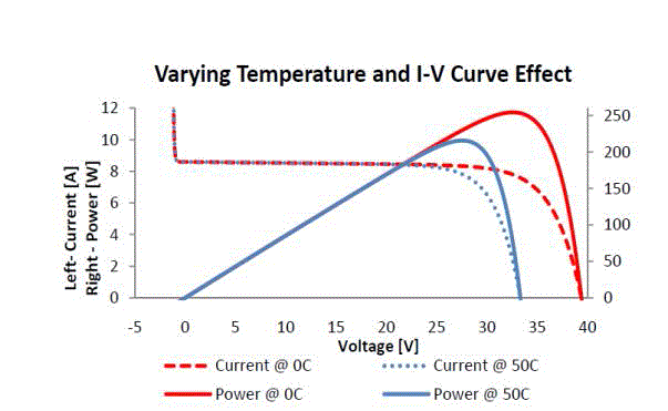
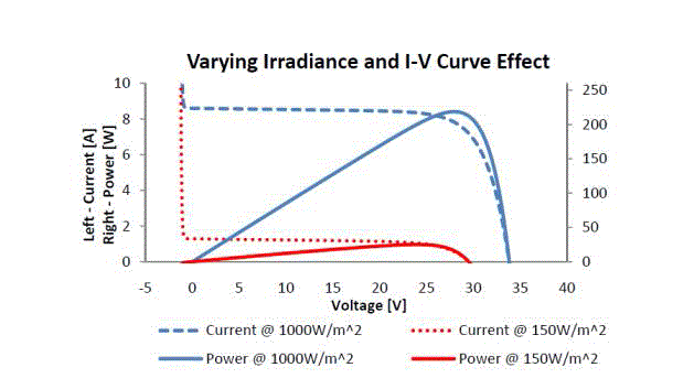
| We can see the effect of various factors that affect the MPP for a Solar array such as partial shading (Fig 3)and temperature effects in the graphs shown in (fig 4). We can see the effect varying irradiance in the fig.5).The P&O algorithm take more time to track the MPP about 15 ms under the optimal condition of radiation, temperature. We can see the characteristics at zero degree and at 50 degree. It is clear that the power will be reduced at higher temperature. The MPP also changes from 34 Volt to about 28 volt and the power also reduced from 245 Watts to 200 Watts. In fig: 5 we can see [5] the voltage current characteristics at different radiation levels of solar energy. We can see the curves at 1000 W/m2 and at 150 watt/m2 radiation intensities. The power is directly proportion to the incident radiation in the panel. We can see the power will be maximum about 230 watts at 1000 W/m2 radiations and it has reduced to 25 Watts at150 W/m2 |
| In the proposed system we are using an algorithm which can be capable of update the voltage not in fixed units but in variable step size in adaptive manner. In this method we are measuring the voltage and current from the input side and the output side and using these values we are predict the next update in the duty cycle. For predicting the update we are using some algorithm like LMS |
| algorithm[11], Normalized LMS [9]Algorithm and RLS algorithm[10]. |
| LMS Algorithm |
 (3) (3) |
| Normalized LMS |
 (4) (4) |
| RLS algorithm |
 (5) (5) |
| Where |
| Wn+1-New update in the PWM deciding factor |
| Wn -Previous value of PWM deciding factor |
| μ-Arithmetic mean up to n’th instant. |
| e(n) -error at n’ th instant |
| X(n) -Noisy input |
| I(n) -actual input |
| B -Constant step size |
| In selecting the step size B in the LMS algorithm, there is a tradeoff between the rate of convergence, the amount of excess mean square error, and the ability of the filter to track signals. Ideally when the adaptation begins and Wn is far from the optimum solution. Then the step size should be large in order to move the weight vector rapidly towards the desired solution. Then as the algorithm begins to converge in the mean to the steady state solution the step size should be decreased in order to reduce the excess mean square error. This suggests the possibility of using a variable step size in the LMS adaptive filter. The difficulty however is in specifying a set of rules for changing the step size in such a way that the adaptive filter has a small excess mean square error while at the same time maintaining ability of the filter to respond quickly to changes in the signal statistics. Assuming that x(n) and d(n ) are real valued process, one approach that has been proposed for changing step size , referred to as the variable step size algorithm(VS)[8],is to use a co efficient update equation of the form |
 (6) (6) |
 (7) (7) |
| .These rules are based on the remains that if the sign of e(n). x(n − k) is changing frequently then the coefficient Wn (k) should be close to its optimum value where the gradient is equal to zero. On the other hand if the sign not changing very often, then the coefficient Wn(k) is probably not close to its optimum value. Therefore μn(k) is decreased by a constant, c1, if m1 successive sign changes are observed in e(n). x(n − k) as the same sign for m2 successive updates in addition hard limits are placed on the step size |
| μmin< μn(k)<μmax |
| In order to ensure that the VS algorithm converges in the mean with only a modest increase in computation, the VS algorithm may result in a considerable improvement in the convergent state. [12] |
| The output from the algorithm (Wn+1) will be given to produce the appropriate PWM signal. So there will be some program that will perform the PWM generation by using the value Wn+1.The Wn+1 value will get from the adaptive algorithm method as shown in the above equations. In the software side there are we have to implement this algorithm, we have to calculate the MPP point at regular time intervals and there will be some methods to produce PWM pulses. Here we used to produce the PWM signal at a frequency of 20 KHZ. So the update can be performed very fast and the tracking will become faster about 5 ms and thus the efficiency and performance improved significantly. |
| This adaptive algorithm has much more noise reduction capabilities and is able to find out the maximum power points and can control the device to bring to the MPP points. It is intelligent enough to avoid the local maxima and to track the true MPP |
SOFTWARE
|
| The algorithm implementation has to realize many problems at the same time. There will be two parts in MPP methods, first, it should calculate the MPP at different conditions at faster and accurate manner .So there should be some timing interval to find out the MPP .Secondly we have to drive the device to work on that MPP points. For the first step we have different adaptive methods to find out the exact maximum power points. We can summarize the steps as follows |
| Step1: it has to find out MPP (this can be done by using the input values of V, I that we measured). |
| Step2: it has to update the Wn+1 using the equation.(Wn+1 can be the new duty cycle. for example previous sample shows that duty cycle is 40,Wn+1 is 41 or 39) |
| Step3: it has to produce PWM pulses using the new Wn+1 value. |
| My plan is these three should be done by my software that written in DSP processor. In our algorithm we can calculate the MPP and can drive to MPP at same time using the adaptive methods. Our software we will measure both input and output power using some sensors and the difference can be used to find out the update in the duty cycle. In some paper step 2 and step 3 are done by Adaptive PID controller. In neural network method [4] it will directly find out the duty cycle by using the input V, I values using some training algorithm. Each voltage and current values corresponding duty cycle will be there. |
| We have implemented this adaptive filter algorithm in the DSP processor. For the practical implementation we used a solar panel(KC85T Solar array)of 36 cell, Voc (21.7v), Isc (5.34A).It can produce maximum power of 87.35 watts. It was seen that the system can perform very well in case of cloudy atmosphere and shading. From the observation it is found that it is working with an average efficiency of 96.9 %. |
CONCLUSION
|
| In this paper we are successfully simulated and implemented the adaptive LMS filter algorithm to perform the maximum power point tracking. It was seen that it is an effective and high performance algorithm. We have seen that this adaptive filter algorithm can track the MPP at faster rate and with maximum accuracy. |
Figures at a glance
|
 |
 |
 |
| Figure 1 |
Figure 2 |
Figure 3 |
 |
 |
 |
| Figure 4 |
Figure 5 |
Figure 6 |
|
| |
References
|
- Byung O Kang and Jae H Park “Kalman Filter MPPT Method for a Solar Inverter”:IEEE 2011
- IEEE JOURNAL OF PHOTOVOLTAICS, VOL. 2, NO. 4, OCTOBER 2012:” Control and CircuiTechniques to Mitigate PartialShading Effects in Photovoltaic Arrays”
- International Journal of Scientific & Engineering Research Volume 3, Issue 3, March -2012 1 ISSN 2229-5518:” Design andImplementation of Maximum Power Point Tracking (MPPT) Algorithm for a Standalone PV System “
- Energy and Buildings 51 (2012) 29–38 Elseveir “Intelligent maximum power point tracking for PV system using Hopfield neuralnetwork optimized fuzzy logic controller”
- “Photovoltaic String Inverters and Shade-Tolerant Maximum PowerPoint Tracking: Toward OptimalHarvest Efficiency and MaximumROI”(December 2010 / White Paper by Dr. Andrew Swingler,Schnieder Electric)
- Ali Nasr Allah Ali1, Mohamed H. Saied, M. Z. Mostaf and, T. M. Abdel- Moneim “A Survey of Maximum PPT techniques of PVSystems”
- Y.Jung et al.,”improved peturbation and observation method(IP&O) of MPPT control for photovoltaic power systems," 2005, pp.1788-1791M. Young, The Technical Writer's Handbook. Mill Valley, CA: University Science, 1989.
- RW Harries,D.M.Chabries and R.A.Bishop “A variable step size adaptive filter algorithm”IEEE transaction on acoust,Speechsig.Proc. Vol.ASSP-34,no.2,pp.309-316,April1986.
- NJ Bershad”Analysis of the normalaised LMS algorithm with Gaussian inputs” IEEE transaction on acoust,Speech sig.Proc.Vol.ASSP-34,pp.793-806,April1986.
- E.Eleftheriou and D.Falconer”Tracking properties and staedy state performannce of RLS recursive Algorithms” IEEE transaction onacoust,Speech sig.Proc. Vol.70 ASSP-34,no.5,pp.1097-1110,Oct1986
- PL Feintuch”An adaptive recursive LMS filter” IEEE transaction on acoust,Speech sig.Proc.IEEE,pp.-1622-1624,Nov1976
- Monson.H.Hayes”Statistical digital signal pocessing and modelling”
- “Comprehensive Approach to Modeling and Simulation of Photovoltaic Arrays” Marcelo Gradella Villalva, Jonas Rafael Gazoli, and Ernesto Ruppert Filho
|