Keywords
|
| low pass filter, Dielectric constant, Microstrip filter, Defected ground structure (DGS) |
INTRODUCTION
|
| With the rapid development of microwave communication systems, microwave low pass filters (LPFs) with low cost, small size, low insertion loss, high selectivity, and wide stop band have attracted wide attention for years. Various technologies have been developed in practice, but the microstrip LPFs are more dominant due to the reduction of circuit sizes. Stepped-impedance structure is a relatively popular way to implement microstrip LPFs by cascading very high and very low characteristic impedance transmission line alternatively. Applications uctiof defected ground structure (DGS) in radio frequency/microwave (RF/MW) circuits find numerous advantages like circuitry size redon and superior response suppression. The conventional DGS element uses a dumbbell-shaped pattern etched in the ground plane This DGS element exhibits a bandgap charactertics at some frequency, which is mainly attributed by a finite attenuation poles. The relationship between attenuation pole frequency and the physical dimensions of the DGS unit was also explored. Recently it usage in the low pass filter for wide stop band implementation has been focused and demonstrated. In fact , these DGS elements with uniform dimensions are cascaded in a one dimensions (1-D) periodic pattern in order to realize wider stop band even the pass band ripple is concerned To counteract this ripple problem, nonuniform configuration have been proposed to achieve much WIDER stopband and smaller passband ripples simultaneously. It is found that the more DGS element are used, the wider stopband is achieved. |
| In this paper low pass filter is optimized for high performance and efficient. Microstrip technology is used for simplicity and easy of fabrication. The design and simulation are performed using 3D full wave Electromagnetic simulator IE3D. |
U-SHAPED DGS UNIT
|
| Despite the different periodic DGS proposed in the past, the main laggard of these approaches is the excess circuitry size introduction due to the cascade DGS configuration . In order to realize simultaneously wide stopband and size minimization for the microstrip low pass filter with DGS a double equilateral U- shaped DGS unit that can offer dual attenuation poles is proposed. The paper control of these two attenuation poles can significantly suppress the spurious response in the stopband with much smaller defected ground area. A microstrip low pass filter prototype with a cut off frequency of 1.5GHz and wide stop band up to 10GHz has been designed and experimentally characterized to demonstrated the proposed DGS usefulness. |
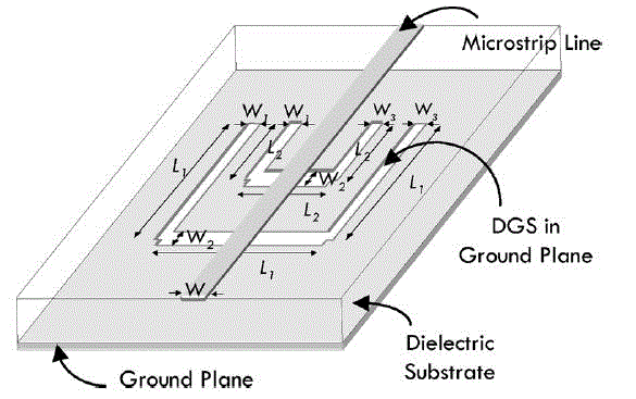
| The proposed double equilateral U shaped DGS unit shown in fig.1, it has a 6-pole ordinary microstrip low pass filter on the top and five equilateral U shaped pattern that are symmetrically etched in the ground plane. Each U shaped pattern consist of three etched lines with the same length but the different width (W1, W2, and W3) by setting these five U shaped pattern with different length (L1,L2 where L1>L2). The smaller one can easily be embedded inside the larger ones with the open end alignment. |
FILTER DESIGN METHOD
|
| The design of low pass filters involves two main steps. The first one is to select an appropriate low pass prototype. The choice of the type of response, including pass band ripple and the no of reactive element will depend on the required specification. The element values of low pass prototype filter, which are usually normalized to make a source impedance g0=1 and a cut off frequency Ωc =1.0,are than transform to L-C element for the desired cut off frequency and the desired source impedance ,which is normally 50 ohms for microstrip filters. The next main step in the design of microstrip low pass filter is to find and appropriate microstrip realization that approximately lumped element filter .The element value low pass prototype with maximally flat response at pass band ripple factor LAR=0.1dB. Characteristic impedance source/load Z0=50ohms , are taken from normalized value gi i.e. g1, g2, g3, g4………..gn. The filter is assumed to be fabricated on a substrate a dielectric constant ?r and of thickness h mm for angular (normalized) cut off frequency Ωc, using the element transformation. |
| A. Filter specifications: |
| Relative Dilectric constant, Er =4.4 |
| Height of substrate, h=1.6 mm |
| The substrate used- |
| The loss tangent tan?=0.02 |
| Input impedence Zo =50Ω |
| Ωc = 1Ω |
| Cutoff frequnecy fc=2.4GHz |
| B. Designe Equation |
| Determine the valus of the prototype elements to realize the specifications. Aiso we have taken the |
 |
 |
 |
 |
| To calculate the width of capacitor and inductor we use the following formula |
| W/h=8 exp(A)/exp(2A)-2 |
 |
| The effective dielctric constant can be found by the following formula |
 |
DIMENTION OF THE FILTER
|
SIMULATED RESULTS
|
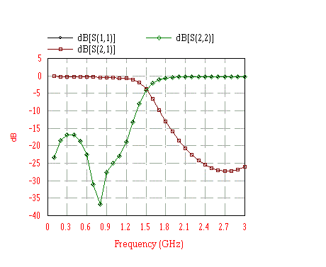
| The proposed filter is composed of sixth-order stepped impedance LPF of varied width and U-shaped DGS unit. The feed line is designed 50 ohm all geometric dimensions are shown in table-1 and fig. 2, 3, 4 shows simulated results of the proposed microstrip low pass filter. For the simulation purpose we have used method of moment based full-wave EM solver IE3D. |
CONCLUSION
|
| The paper present an efficient approach to improve conventional stepped impedance lowpass filter transition band performance with a miniaturized area. from the simulated results the lowpass filter based on the proposed DGS unit offers significant improvement of the stopped band attenuation and size reduction when compared with the conventional low pass filter. Thus this method is very flexible for configuration and specially use full low pass filter design to develop sharp transition band. |
ACKNOWLEGEMENT
|
| The authors would like to thank authorities of GGCT college Jablapur and MITS Gwalior for all the support provided. The guidance facility provided by Dr. P. K. singhal and Proff. Avinash Gaur. |
| |
Tables at a glance
|
 |
| Table 1 |
|
| |
Figures at a glance
|
 |
 |
 |
 |
| Figure 1 |
Figure 2 |
Figure 3 |
Figure 4 |
|
| |
References
|
- D.M. Pozar ”Microwave Engineering”, John Wiley, 2000.
- “IE3D user’s Manual,” Zeland Software, Inc. , Jan. 2001, Release 8
- S. Pirani, J. Nourinia, and C. Ghobadi, “Small ultra wide band pass filter with notched band,” IEEE Microw. Wireless Compon. Lett., Vol. 20, no. 8,pp. 444-446, Aug.2010
- R. Ghatak, P. Sarkar, R. K. Mirshra, D. R. Poddar, “a compect ultra wide band pass filter with embadedm SIR as band notch stucture,” IEEE Microw.,wireless compon.,lett., vol. 21, no. 5, pp261-263, may 2011.
- S.Sun and L. Zhu, “multimode resonator based band pass filter ,” IEEE Microw., Mag., vol.10, no.2, pp.88-98, april 2009.
- B. Yao, Y. Zho, Q.Cao, and Y.Chen, “compact Ultra wide band pass filter with improved upper stop band performance,” IEEE microw., wirelesscompon., lett. , vol. 19, no.1,pp.27-29, jan 2009.
- J.Garcia-Garcia, J. Bonache,and F. martin, “application of electromagnetic band gap to design of ultra wide band pass filters with good out of the bandperformance,’ IEEE trans micro. Theoty Tech., vol 54,no.12, pp.4136-4140, dec.2006.
|