Keywords
|
| Induction motor, drives, ZigBee, AC drives system, inverter, PWM |
INTRODUCTION
|
| The three phase voltage-fed pulse width modulated inverters are recently showing popularity for multi-megawatt industrial drive applications. The main reasons for this popularity are easy sharing of large voltage between the series devices and the improvement of the harmonic quality at the output as compared to a two level inverter. A variable speed drive is a device used to provide continuous range process speed control (as compared to discrete speed control as in gearboxes or multi-speed motors) and is capable of adjusting both speed and torque from an induction motor (IM). The project is aimed at controlling speed of 3-phase induction motor using ZigBee wireless control protocol. ZigBee wireless technology is a specification for a suite of high level communication on protocols using small, lowpower digital radios based on IEEE 802 standard. |
| ZigBee is targeted at applications that require a low data rate, long battery life and secure networking. ZigBee operates at 2.4GHz worldwide. Transmission range is between 10 and 75 meters (33 and 246 feet) and upto 1500 meters for ZigBee. Its specification is intended to be simpler and less expensive than other WPANs such as Bluetooth. |
| There are several methods for the speed control of an induction motor such as frequency variation, pole changing, variable stator voltage, variable rotor resistance, constant V/f control, slip recovery method etc., the most widely used method is constant V/f speed control method. In this method, the V/f ratio is kept constant which in turn maintains the magnetizing flux constant so that the maximum torque remains unchanged, there by the magnetic saturation problem can be eliminated. |
| Objective |
| In this paper, wireless speed control of AC drive system is discussed. This system includes contolling the speed of the three phase induction motor, in order to control the speed of the induction motor we are using proximity sensor. |
| This system uses the digital controller dsPIC30F4011 for controlling the system operation. The controller unit collects the speed values of the three phase induction motor from proximity sensor and processes it. The dsPIC30F4011 controller is programmed to generate sinusoidal PWM pulses according to speed values obtained from the sensor. The controller processes the information from sensor and check whether the desire speed is reach or not, then the controller generates PWM pulses according to the feedback value. After processing the information from the sensor, the control unit sends the data to display. |
| The implementation of the project is shown in the block diagram. DC supply is applied to microcontroller. Totally six number of pulses are generated by the DSPIC30F4011 controller. Three-phase inverter is used to get the threephase input. In this inverter three branches are available. Each branch belongs to each phase. Each branch has two devices. The output of three-phase inverter has variable voltage and variable frequency. Speed control is done by varying the frequency of the system using ZigBee transeiver. The speed of the three-phase motor varies. If we change the frequency alone it will affect the torque of the motor. To avoid this we will change the voltage proportional to the frequency changes. This type of control maintains the motor speed constantly. The PWM pulses are given to input of optocoupler. Optocoupler is used to isolate between control circuit and inverter circuit. DC supply is applied to inverter circuit. Optocoupler output signal is inverted from original PWM input signal. Optocoupler output is given to driver circuit through NOT gate (NOT gate output signal same as the original input signal). Load is connected across the inverter circuit terminals. The PI controller is used to maintain the constant motor speed and motor speed is display to LCD. |
HARDWARE DESIGN
|
| The wireless speed control of AC drive system consists of a DSPIC30F4011 controller, sensor unit, display unit, power supply unit and ZigBee transeiver. The microprocessor gets the speed value of the three phase induction motor from proximity sensor and based on this value, it generates PWM pulses to the inverter. |
| 3.1 Block Diagram |
| The block diagram of the wireless speed control of AC drive system is shown in the following figure. It includes a DSPIC30F4011 controller, sensor unit, display unit, power supply unit, optocoupler, driver unit ZigBee transeiver. Here the personal computer and ZigBee transeiver are connected through RS232 in the controlling section. |
| 3.2 Microcontroller |
| The digital controller DSPIC30F4011 is a general purpose 16 bit digital controller which is used to combine the calculation capability of digital signal processor and controlling capability of PIC microcontroller, to achieve precise control. DSPIC30F4011 has high performance modified RISC CPU. The controller has a C compiler optimized instruction set architecture with flexible addressing modes. This controller is used to generate PWM pulse to control the speed of the motor by collecting speed values from sensor. |
| 3.3 Proximity Sensor |
| Inductive type proximity sensor is coupled near the shaft of the three phase induction motor which used to sense the rotation of the motor and gives the values to the DSPIC30F4011 controller. |
| 3.4 Display unit |
| LCD display unit is used to display the datas sent to microcontroller by the sensor. LCD displays 8 lines with 21 characters in each line. |
| 3.5 Driver unit |
| The triggering circuit is nothing but a switch which alerts the supply to the induction motor by turning on/off, on application of the gate pulse coming from the ccpl pin of the controller. |
| 3.6 ZigBee module |
| ZigBee transceiver module contains ZigBee transmitter and ZigBee receiver. The Xbee RF Modules are designed to operate within the ZigBee protocol and support the unique needs of low-cost, low-power wireless sensor networks. The modules require minimal power and provide reliable delivery of data between remote devices. The modules operate within the ISM 2.4 GHz frequency band. It operates over a range of 100-200 meters. The receiver module consists of a Xbee RF module which is connected to computer system. Thus the monitoring data received by ZigBee module is directly transferred to computer system. |
DESIGN METHODOLOGY
|
| The values of the inductance and the capacitor are greatly dependent upon the rating of the motor, whose speed is to be regulated. Therefore the motor ratings are, 3-phase induction motor, power 0.75KW, star connected, speed - 1390 rpm voltage - 415V, current - 1.80 A, frequency - 50Hz, efficiency - 75%. For making the design calculation easy assume shoot through duty ratio D=5% of total time period. |
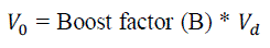
| From the rectifier output and required inverter input, the boosting factor can be calculated using the following relation. |
 (1) (1) |
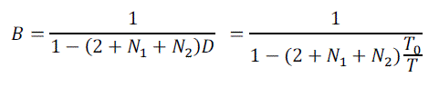
| The inverter`s boosting factor B is given by |
 (2) (2) |
| Where D is the shoot through duty ratio, T0 is the shoot through time interval during the switching period T and N1 and N2 are turns ratios of the transformers T1 and T2, respectively. From (2) it is clear that B mainly depends on D, N1 and N2, so high boosting capability can be achieved by adjusting the turns ratio of the transformer with small shoot through duty ratio. Since the shoot through duty ratio is small, the modulation index (M) can be improved thereby the output power quality will be improved. |
| Turns ratios N1 and N2 can be calculated using equation (2) after the boosting factor is determined. Since we are considering the network as symmetric take both quantity N1 and N2 as same. |
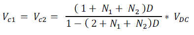
| The design of capacitance mainly depends on the ripple voltage. We know that capacitor ripple voltage is 1 to 10% of voltage across the capacitor. In order to reduce the ripple assume ΔVc1 and ΔVc2 are 1% of Vc1 and Vc2 respectively. By applying KVL in both active and shoot through state, it is possible to calculate voltage across the capacitor and is given by |
 (3) (3) |
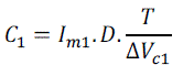
| After finding the voltage across the capacitor, it is possible to find the value of capacitors from the following equations. |
 (4) (4) |
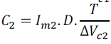 (5) (5) |
| Where Im1 and Im2 are the magnetizing currents and the sum of this current is equal to the load current. Since the circuit is symmetric, take the values of both capacitors as same. The magnetizing inductance for the transformer can be calculated from the following equations. |
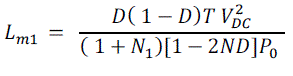 (6) (6) |
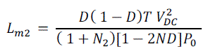 (7) (7) |
| The ouput of the AC drive system circuit is given to the three phase induction motor. The three phase inverter is of two types : 120° mode voltage source inverter and 180° mode voltage source inverter. The 120° mode voltage source inverter is used for the simulation purpose. |
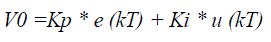
| 4.1 PI Controller |
| The interface circuit and the software for control operation are designed with consideration of a short sampling time to achieve a better performance. In order to make the control algorithm executable in real time, a simple PI control algorithm has been developed. Timer overflow interrupt has been used instead of polling to help to shorten the calculation time. |
| The implementation of the PI controller has been done by writing the assembly language program. The digital controller parameters were selected purely from the stand point of the performance and physical realization in the analytical and theoretical sense |
| The output of the PI -controller is V0 |
 (8) (8) |
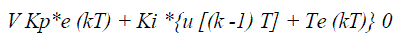 (9) (9) |
| The PI algorithm uses a new tool to generate an analog like output directly from the microcontroller without using any DAC (digital to analog converter). This technique is known as the PWM (Pulse Width Modulation). In PWM a square wave is generated with a constant frequency, the change in the On-Time or Off-Time of the square wave changes the average output i.e. the change in duty cycle changes average output. The following equation shows the relation between duty cycle and average output voltage: |
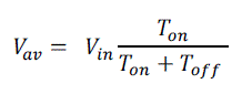 (10) (10) |
| With PI algorithm features, the microcontroller generates PWM with varying duty cycle resulting effective control action signal across the motor which is analogous to the output signal of PI controller which helps the motor to reach steady state condition, steady state error become zero. The values of p K and i K were determined by trial and error method in order to get the better transient response with nearly zero overshoot. Accurate and fast positioning of motor has been achieved by using microcontroller-based PI controller. |
| 4. The DSPIC30F4011 microcontroller based three phase induction motor speed control is investigated through simulation with the help of MATLAB 7.10 Simulink. Simulink is a software package for modeling, simulating, and analyzing dynamic systems. Figure 5.1 shows simulation circuit diagram of the wireless speed control of AC drive system. |
RESULTS OF SIMULATION USING MAT LAB SOFTWARE
|
| The schematic representation of the wireless speed control of AC drive system is designed by using the MatLab software and the code is done through compiler software. Here the result is represented as three figures, 6.1) Simulated Result for the speed of the three phase induction motor, 6.2) Output waveform of the Inverter, 6.3) Simulated waveform of Pulse width modulation. |
HARDWARE OF WIRELESS SPEED CONTROL OF AC DRIVE SYSTEM
|
| The images of the hardware of the wireless speed control of AC drive system are provided in this section. Figure 7.1 shows the microcontroller section and inverter section which is connected with the three phase induction motor. |
| Figure 7.2 shows the controlling section of wireless speed control of AC drive system which includes ZigBee transceiver section connected with the computer system through RS232 serial cable. |
CONCLUSIONS
|
| Wireless speed control of AC drive system circuit simulated in MATLAB showed desirable results for speed. Hence, it was further implemented in hardware. The hardware makes use of ZigBee protocol for communicating the PWM control signals from the microcontroller to the inverter, where the control signal is carrier based sinusoidal PWM. Thus, speed of motor (1390rpm) can be effectively controlled by using the designed hardware setup. |
| |
Figures at a glance
|
 |
 |
 |
 |
| Figure 3.1 |
Figure 4.1 |
Figure 5.1 |
Figure 6.1 |
 |
 |
 |
 |
| Figure 6.2 |
Figure 6.3 |
Figure 7.1 |
Figure 7.2 |
|
| |
References
|
- Qazalbash A, Awais Amin, Abdul Manan, Mahveen Khalid, “Design and implementation of microcontroller based PWM technique for sine wave inverter” 2009.
- Emil Levi, “comparison of carrier-based and space vector PWM techniques for three-level five-phase voltage source inverters”, 2010.
- Nalin Kant Mohanty, RanganathMuthu , ‘Microcontroller based PWM controlled four switch 3-phase inverter fed induction motor drive’,SERBIAN JOURNAL OF ELECTRICAL ENGINEERING Vol. 7, No. 2, November 2010, 195-204, 2010.
- Andrew M. Knight, “a comparison of inverter losses with sinusoidal pulse width modulation (PWM), space vector PWM and discontinuous PWM (DPWM)”, 2011.
- S.M.Wankhede, R.M.Holmukhe, Miss.A.M.Kadam, Miss.P.Rshinde, P.S. Chaudhari, “Microcontroller based control of 3-phase induction motor using pwm technique”, International Conference on Electrical Energy and Networks (ICEEN 2011), 2011.
- M.S.Aspalli, Asha.R, P.V. Hunagund, “3-phase induction motor drive using IGBTs and constant V/F method”, International Journal of Advanced Research in Electrical, Electronics and Instrumentation Engineering Vol. 1, Issue 5, November 2012.
- AmolSutar, SatyawanJagtap, “Advanced 3-phase PWM inverter control using microcontroller”, IOSR Journal of Electrical and Electronics Engineering (IOSR-JEEE) e-ISSN: 2278-1676 Volume 5, Issue 2 (Mar. - Apr. 2013), PP 21-28, 2013.
- Hao Liang, Bong Jun Choi, WeihuaZhuang, Xuemin (Sherman) Shen,“Stability enhancement of decentralized inverter control through wireless communications in microgrids”, 2013.
- D. Soumiya,“a monitoring and control of a PLC based VFD fed three phase induction motor for powder compacting press machine”, 2013.
- Mohit Kumar, Mohnish Sharma, Rishabh Narayan, Sumit Joshi, Sanjay Kumar, “ZigBee based parameter monitoring and controlling system for induction machine”, Conference on Advances in Communication and Control systems 2013(CAC2S 2013).
- A.M.Jain, P.S.Joshi “Wireless speed control of an induction motor using PWM technique with GSM”, IOSR Journal of Electrical and Electronics Engineering (IOSR-JEEE) e-ISSN: 2278-1676,p-ISSN: 2320-3331, Volume 6, Issue 2 (May. - June. 2013).
- SheebaJoice C, S. R. Paranjothi, V.JawaharSemthil Kumar, “Digital control strategy for four quadrant operation of 3-phase BLDC motor with load variations”, IEEE TRANSACTIONSON INDUSTRIAL INFORMATICS, VOL.9, NO.2, MAY 2013.
- Dong Ho Shin, “Single chip dual plate capacitive proximity sensor with high noise immunity”, IEEE SENSORS JOURNAL, VOL. 14, NO. 2, FEBRUARY 2014
- www.datasheetcatalog.com.
|