This paper presents the regualtion of the active and reactive powers in a grid connected Doubly Fed Induction Generator(DFIG) based Wind Energy conversion System (WECS). A back to back PWM converter setup with stator flux oriented vector control is used to control the DFIG. The constituents of the WECS are mathematically modelled in MATLAB/SIMULINK . The back to back PWM converter set up consists of the Rotor Side Converter (RSC) and the Grid Side Converter (GSC) with intermediate DC link .Decoupled control of the DC link voltage and the grid reactive power is obtained through Voltage oriented control (VOC) of GSC. Similarly independant control of power from wind and reactive power of DFIG is carried out by stator flux oriented vector control of RSC. Coordinated control of the back to back converter setup in both subsynchronous and supersynchronous mode is presented. Maximum power is captured at all wind speeds by controlling DFIG torque and overall power factor of the system is maintained to be unity.
Keywords |
| Wind Energy Conversion System( WECS ),Doubly Fed Induction Generator(DFIG), Stator
flux Oriented Vector Control, VOC (Voltage oriented control ) |
INTRODUCTION |
| Among renewable sources, wind power systems have developed to be prominent suppliers of electrical
energy with exponential increase both in unit power ratings and overall capacity. Because of the randomness
of wind speed in different areas, a flexible electric generation system is required to maintain constant
frequency voltage and stable power. In Grid connected systems the wind energy system is connected to
existing grids. The voltage and frequency of the system is fixed by the grid. Doubly fed induction machine
(DFIM) based wind turbines have undoubtedly arisen as one of the leading technologies for wind turbine
manufacturers, demonstrating that it is a cost effective, efficient, and reliable solution. They have been widely
used in modern wind energy systems, due to the advantages of variable speed operation in both sub
synchronous and super synchronous operation , fractional rated power converters, four quadrants active and
reactive power capabilities. |
DFIG MACHINE MODELLING |
| The DFIG machine is modeled in the dq reference frame. The d axis is oriented along the stator flux vector.
Hence the variables with angular frequency equal to the frequency of the stator flux appear as DC variables. |
| By orienting the reference frame along the stator flux the various variables are derived as follows |
 (1) (1) |
 (2) (2) |
 (3) (3)
|
 (4) (4) |
 (5) (5) |
 (6) (6) |
 (7) (7) |
 (8) (8) |
 (9) (9) |
 (10) (10) |
 (11) (11) |
 (12) (12) |
| The Electrical power generated by the machine is given by |
 (13) (13) |
 (14) (14) |
| Hence Electrical torque can be expressed as , |
 (15) (15) |
CONTROL STRATEGIES FOR GRID SIDE AND ROTOR SIDE CONVERTERS |
| Control of DFIG for proper and efficient conversion of wind energy is necessary and unavoidable. It
maintains magnitudes of the generator, such as torque, and active and reactive power, and also magnitudes
related to the grid side converter, such as the reactive power and the DC bus voltage close to their optimum
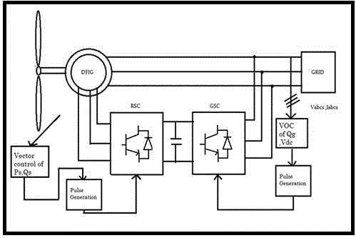
values.A typical DFIG-based Wind Energy Conversion System (WECS) comprises, the wind turbine
(including gearbox), DFIG, and back to back converters connected to the grid. The stator of the DFIG is
directly connected to the grid. The rotor of the DFIG is connected to the grid through the back to back
connection of rotor side converter and grid side converter. A dc link capacitor is connected between the two
converters. The block diagram of this system is shown in figure 1. Grid Side Converter(GSC) employs
Voltage oriented control(VOC) and the Rotor Side Converter(RSC) employs stator flux oriented vector
control. |
A. Voltage oriented vector control of GSC |
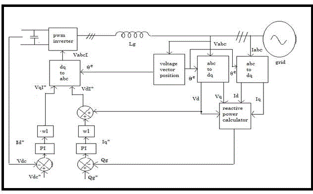
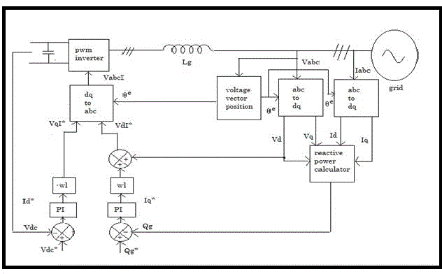
| The objective of the supply-side converter is to keep the DC-link voltage constant regardless of the
magnitude and direction of the rotor power. A vector-control approach is used, with a reference frame
oriented along the stator (or supply) voltage vector position, enabling independent control of the active and
reactive power flowing between the supply and the supply-side converter. The PWM converter is current
regulated, with the direct axis current used to regulate the DC-link voltage and the quadrature axis current to
regulate the reactive power. Thus supply-side PWM converter is used to regulate the reactive power of the
system. The figure 2 shows the schematic of voltage oriented control . |
| The voltage balance across inverters is |
 (16) (16) |
| In the dq reference frame , rotating at the supply angular frequency , with the d axis overlapping with the
supply voltage vector the grid voltage is given as , |
 (17) (17) |
 (18) (18) |
| The expression for grid side real and reactive power are |
 (19) (19) |
 (20) (20) |
| By power balance equation |
 (21) (21) |
| It is seen that the DC-link voltage can be controlled via idg.The control scheme utilizes current control
loops for the d axis and q axis grid current with the d axis current demand being derived from the DC-link
voltage error through a standard PI controller. The q axis current demand determines the displacement factor
on the supply-side of the inductors. |
| The reference d q voltages for the grid side converter are |
 (22) (22) |
 (23) (23) |
| The angular position of the d axis of the grid voltage can be found as |
 (24) (24) |
| B. Stator flux oriented vector control of RSC |
| In vector control of a DFIM, the components of the d and the q axis of the rotor current are regulated. If a
reference frame orientated with the stator flux is used, the active and reactive power flows of the stator can be
controlled independently by means of the quadrature and the direct current .There is no need to know the
rotor-induced EMF. Since the stator is connected to the grid, and the influence of the stator resistance is
small, the stator magnetising current can be considered constant.The control schematic is shown in Fig 3.
The relation between stator and rotor currents are |
 (25) (25) |
 (26) (26) |
| By stator flux orientation simplified voltage , flux and power equations are |
 (27) (27) |
 (28) (28) |
 (29) (29) |
 (30) (30) |
 (31) (31) |
 (32) (32) |
| Under stator-flux orientation, the relationship between the stator real and reactive power and rotor currents
can be written as |
 (33) (33) |
 (34) (34) |
SIMULATION ANALYSIS |
| The power regulation of the developed DFIG model is analysed in supersynchronous and subsynchronous
modes using MATLAB/SIMULINK . |
| The DFIG machine used for analysis is modelled using dq reference frame and the various internal
parameters are listed in Table 1. The simulation of DFIG based WECS is carried out without any controls for
the GSC and RSC to test the developed dq model of the DFIG. The Machine is run at 1650 RPM and torque
of -50 N-M for supersynchronous generating mode and the oscilloscope waveforms for stator and rotor
currents , stator and rotor real powers, speed and torque are shown below in figure 4(a)-(c).It can be
observed that during supersynchronous operation bothe the stator and rotor real powers are negative.Hence
power is fed to the grid from stator as well as rotor. |
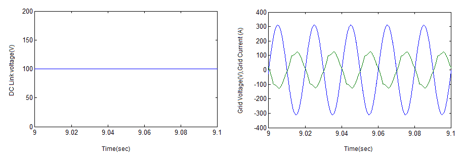
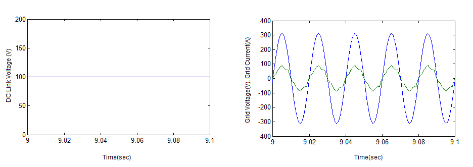
| During vector control of the WECS a 1:6 step down transformer is connected between the grid and the grid
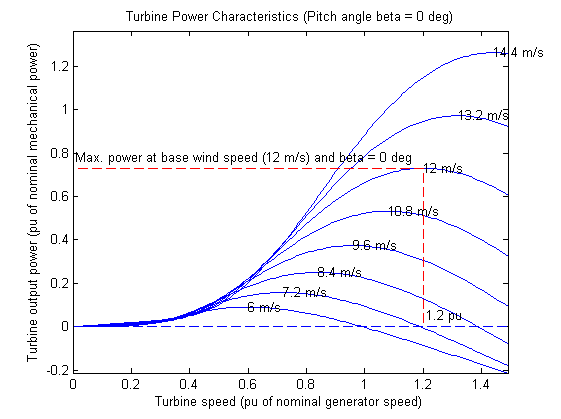
side converter and the DC link voltage is maintained at 100 V .The wind turbine characteristics is shown in
Fig 7. The grid side reactive power is set as 0 the relation between the grid voltage and grid current is shown
for supersynchronous and subsynchronous mode is shown in fig 5 & 6 respectively.During supersynchronous
mode power is fed from the DFIG rotor to the grid while in subsynchronous mode power is drawn from the
grid . Hence the change in power flow direction can be seen as 180 o phase shift between the grid voltage and
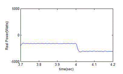
grid current .A step change in windspeed is given from 7.2 m/s to 8.4 m/s at 4 sec and regulatory response
observed in stator real power as shown in fig 8 . |
CONCLUSION |
| Power regulation of a grid connected Wind energy conversion system with DFIG has been presented for
varying wind speeds in this paper. A back to back PWM converter is employed between the wind turbine
driven DFIG and the grid in order to control the power flow from the Wind turbine to the grid. Stator flux
oriented vector control is employed in the rotor side converter to decouple the active and reactive power
control of the DFIG. Grid voltage oriented vector control is employed in the grid side converter to maintain
constant DC link voltage for effective power flow and to maintain overall system power factor as unity .It is
shown that with variations in wind speed the system automatically captures the maximum power possible for
tat speed and the regulatory control is done within milliseconds. During change over between super
synchronous and sub synchronous operations the back to back converters automatically shift between their
operation as inverters and converters. The grid reactive power is maintained close to 0 from sub synchronous
to super synchronous speeds. |
| |
Tables at a glance |
 |
| Table 1 |
|
| |
Figures at a glance |
 |
 |
 |
 |
 |
| Figure 1 |
Figure 2 |
Figure 3 |
Figure 4a |
Figure 4b |
 |
 |
 |
 |
 |
| Figure 4c |
Figure 5 |
Figure 6 |
Figure 7 |
Figure 8 |
|
| |
References |
- R. Pena, J.C.Clare and G. M. Asher, âÃâ¬ÃÅDoubly fed induction generator using back-to-back PWM converters and its application to variable speed wind-energy generationâÃâ¬Ã IEE Proc.Electr. Power Appl., Vol. 143, No 3, , May 1996, pp 231-241.
- Guofeng Yuan, Jianyun Chai and Yongdong Li, âÃâ¬ÃÅVector control and synchronization of doubly fed induction wind generator systemâÃâ¬Ã in Power Electronics and Motion Control Conference, vol. III, Aug 2004, pp .886 âÃâ¬Ãâ 890.
- Haisheng Sun, YongfengRen and Hanshan Li,âÃâ¬Ã DFIG wind power generation based on back-to-back PWM converterâÃâ¬Ã Mechatronics and Automation, ICMA , Aug.2009, pp. 2276 - 2280.
- Gonzalo Abad, JesuÃâôs Lopez, Miguel A. RodriÃâôguez, Luis Marroyo and GrzegorzIwanski,âÃâ¬ÃÂDoubly Fed Induction Machine âÃâ¬Ãâ Modelling and control for wind energy generation âÃâ¬ÃÅ,IEEE Press,2011.
- Shuhui Li ,Timothy A. Haskew, Keith A. Williams, and Richard P. SwatloskiâÃâ¬Ã Control of DFIG Wind Turbine With Direct- Current Vector Control ConfigurationâÃâ¬Ã IEEE Transactions on sustainable energy, Vol.3,No.1,January 2012.
- KaimaBouHiam and AkkilaBoukhelifaâÃâ¬Ã Output Power Control of a Wind Energy Conversion System Based on a Doubly Fed Induction GeneratorâÃâ¬ÃÂIEEE,2013
- Yongsu Han, Sungmin Kim, Jung-Ik Ha and Wook-Jin Lee,âÃâ¬Ã A Doubly Fed Induction Generator Controlled in Single-Sided Grid Connection for Wind TurbinesâÃâ¬Ã IEEE Transactions on energy conversion, VOL. 28, NO.2,June2013,pp.413-423.
|