Keywords
|
| Doubly Fed Induction Generator (DFIG), Pulse width modulation (PWM), Rotor side converter (RSC), Grid side converter (GSC) |
INTRODUCTION
|
| The renewable energy sources like solar cell, wind mills, biomass and geothermal energy are now become the most favorable choices for the researcher. Hence not only in India but the world over, the renewable sources of energy are being utilized in a big way. Among all these renewable energy sources, wind energy has acquired it’s a unique place and playing a big role for generation and control over the energy flow in power system under different operating conditions. |
| Active Power compensation of grid through wind turbine can also enhance the utilization of wind energy and its contribution in the energy sector also improves the performance of the system. Power generation through wind mills are being adopted by so many counties. Now, this became the primary source of electrical power generation in many places over the world. In the power system, normally, for the compensation of active power flow conventional techniques are used, in which, governor’s settings are changed to control active power flow in the grid, consequently, grid frequency can be controlled. Excess uses of non linear loads are creating problems for the interconnected system as far as their proper functioning are concerned. Hence, only by changing the governor’s position active power compensation will not be the feasible option for all times. |
| Therefore, it would be better if the change in active power demand are compensated by renewable energy source like wind farms rather than change in governor’s position of the synchronous generator. Wind turbine along with doubly Fed induction Generator can control the flow of active power in the grid. Grid frequency of Power system depends upon active power flow, by compensating of active power demand grid frequency can be controlled and able to maintain its desired value. Controlling of active power flow can be achieved by rotor conductor through the switching of rotor side converter. Switching techniques are used to generate signals which depend upon a PWM generator. |
RELATION BETWEEN ACTIVE POWER AND FREQUENCY
|
| Equation no. 1 shows a relation between active power and load angle. |
 …………………… (1) …………………… (1) |
| Equation no. 2 shows a relation between reactive power and load angle. |
 ……………… (2) ……………… (2) |
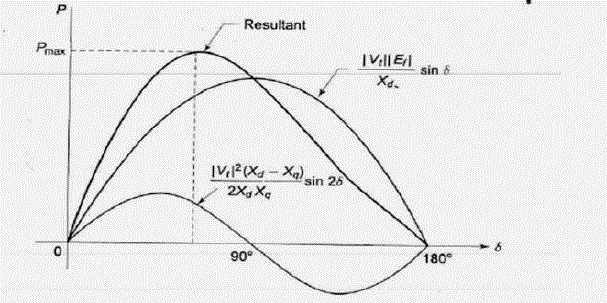
| Fig.1 shows the relation between load angle and active power flow in power system. Load angle represents the relative motion between rotating rotor flux at rotor speed ?r and rotating stator flux which is revolving at the synchronous speed ωs, in case when machine working as generator, rotating rotor flux leads to stator flux by load angle and to compensate the active power demand change in the governor’s position is took place by which rate of steam flow can be changed, hence, there is a change in the mechanical power which is to be developed in the rotor, consequently, the active power regulation will be done. [9] |
| As the active power demand at load side increases or decreases, corresponding change occurs in the frequency of the grid because rotor still responding according to the previous active power demand, therefore, relative angular speed between rotor flux and stator flux will also be changed by load angle, ?. Hence, there must be changed in the governor’s position as the new demand. [1]. |
| In case, when the change in active power demand does not affect governor’s position, this is the time when generating station operates at maximum optimum condition of working. This technique can be achieved by compensating of active power though renewable energy sources like wind turbine. Hence, the support of wind turbine to balance the active power demand of system will be more suited as compare to change in position of governor. |
MODELLING OF DFIG
|
| A. MODEL OF WIND TURBINE |
| This part of the system is directly attached with wind and convert wind energy into rotating mechanical energy of turbine. This part equipped with wind blade, these blades are designed to obtain unequal pressure. At the adjacent side of wind blade when air passes and creates force to move blades at particular direction which causes rotational motion and shaft which connect gear box and wind blade is given equation as |
 ....................................... (3) ....................................... (3) |
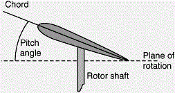
| This developed mechanical power supply to the rotor shaft due to coupling between rotor and gear box. This mechanical power develop can control by pitching of wind on the blade this pitching can be controlled by controlling of pitching angle of blade. Thus, developed mechanical power can be controlled adjusted by pitching angle. |
| By controlling the pitching angle the speed of the turbine can be regulated and made it as suitable as like a conventional synchronous generator for compensating active power demand. |
| B. MODEL FOR DOUBLY FED INDUCTION GENERATOR |
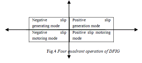
| Doubly Fed Induction machine is an induction machine which has four mode of operation where it can work as a generator and as a motor in both positive slip and negative slip region. |
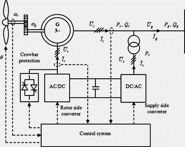
| Both stator and rotor of DFIG are connected with the grid where Stator winding is directly connected while, rotor winding is also connected with grid via a back to back 3 phase voltage source converters. A capacitor of high rating (Cdc) connects these two converters and power is flowing through these winding depends upon torque and flux developed in machine [8]. |
| The back to back converter is having two converters. One of these converters is connected to the grid side which is known as grid side converter (GSC) and the other converter is connected to the rotor side which is known as rotor side converter (RSC) [8]. |
| Grid side converter controls reactive power flow during the fault condition and maintains the voltage of DC link capacitor during normal operating condition. Hence, grid side converter acts as a rectifier during normal operating condition and as an inverter during fault condition. Rotor side converter control active power and reactive power flow in DFIG by application of vector control method [11]. |
| As grid frequency depends upon active power flow and grid voltage depends upon reactive power flow. By controlling active and reactive power flow we can control the frequency and voltage of gird. |
| To study the control of three phase current one method is applied in which 3 phase grid currents ia,ib,ic are converted into direct axis current id and quadeture axis current iq. |
| This method is known as vector control method. The main idea behind this vector control method of an induction motor is to control the torque and flux of the induction machine as same as in DC machine [2]. |
 ...................... (4) ...................... (4) |
| In vector control method, the torque and flux of the motor is controlled, independently. To achieve this magnitude and phase of rotor current are controlled by the pair of DC link capacitor and rotor side converter. By controlling the switching, power switches are connected to the converter, the direct axis current (Id) and quadreture axis current (Iq) can be controlled, so active and reactive power developed in doubly Fed induction Generator can also be controlled. These signals used for switching of power switches and are obtained by pulse width modulation generator [3]. |
MATHEMATICAL MODELING OF DFIG
|
| Active power of rotor Pr and active power of stator Ps are related with the mechanical torque and speed of rotor ωr as well as stator flux field ωs as |
 …………………………… (5) …………………………… (5) |
 …………………………….. (6) …………………………….. (6) |
| In lossless condition |
| Tm=Tem |
| But |
 ……………………………… (7) ……………………………… (7) |
| Where |
 ………………………………… (8) ………………………………… (8) |
| Torque equations |
 ….…………(9) ….…………(9) |
| Ratting of wind turbine based doubly fed induction generator is 7500VA, 440 V. |
OPERATION OF WIND TURBINE BASED DFIG SYSTEM
|
| Doubly fed induction generator basically operates in four mode of operation [10] |
| 1. Positive slip generating mode of operation for first quadrant operation. In this mode of operation speed of rotor is less than stator flux speed and flow of power is from DFIG to grid. |
| 2. Negative slip generating mode of operation for second quadrant operation. In this mode of operation speed of rotor is more than stator flux speed and flow of power is from DFIG to grid. |
| 3. Positive slip motoring mode of operation for third quadrant operation. In this mode of operation speed of rotor is less than stator flux speed and flow of power is from grid to DFIG. |
| 4. Negative slip motoring mode of operation for forth quadrant operation. In this mode of operation speed of rotor is more than stator flux speed and flow of power is from grid to DFIG. |
| The direction of power flow either from DFIG to grid in generating mode operation or from grid to DFIG in motoring mode operation, can be controlled by switching of power switches, which are connected at the rotor side converter during normal operating condition. Therefore, for changing modes of operation of DFIG require switching action. |
| To control the active power flow by DFIG consider equation 1. This equation relates direct axis reactance and active power flow in grid via DFIG. Active power generation and direct axis reactance are inversely proportional. Here, current in direct axis path is considered as direct axis current, which have inversely proportional to the direct axis reactance. On the basis of above discussion direct axis current and active power are related and proportional with each other. Thus, to regulate the active power flow in the circuit the controlling over direct axis current must be taken place. |
| Active power and reactive power flow of grid and measurement and output are given in equation no. 10 and 11. [6] |
 .......................................(10) .......................................(10) |
 .......................................(11) .......................................(11) |
| Mathematical conversion of vector control method and active and reactive power flow in stator winding direct axis current (Ids) and quadeture axis (Iqs) current are given in equations, mentioned bellow. [6] |
 .......................................(12) .......................................(12) |
 .......................................(13) .......................................(13) |
| Similarly, equation no. 14 and 15 are shown direct axis rotor quantities and quadeture axis rotor quantities and active and reactive power of rotor. [6] |
 .............................................(14) .............................................(14) |
 ............................................(15) ............................................(15) |
| The overall active power and reactive power generation of DFIG can be controlled by controlling direct axis quantities and quadeture axis quantities. This paper mainly concern to active power compensation. Hence, all control methodology is applicable to direct axis quantities only. |
CONTROLLING OF FREQUENCY BY WIND TURBINE BASED DOUBLY FED INDUCTION GENERATOR
|
| The controlling of active power generation of DFIG is based on PID controller. In first step of controlling actual value of active power of grid (Pg) is compared with new demands of active power (Pd). This comparison provides error signal, which is known as active power error (Pe). This error signal is fed into the PID controller. |
| Output of PID controller provides required value of active power. For the calculation, the error signals have been generated by comparison of the actual value of active power to demand value of active power. Pr is fed into a mathematical calculation in which value of line current is calculated. This value of line current is required for compensation of change in active power of grid and demand. |
| The value of line current (Ir) is again entered into a mathematical calculation of vector controlling method through which exact values of direct axis current (Idr) and quadeture axis current are obtained. |
| The actual value of grid current is fed for mathematical calculation of vector controlling method by which actual value of direct axis grid current (Idg) and quadeture axis grid current (Iqg) can be calculated. The value of direct axis grid current (Idg) is then compared with requires value of direct axis current (Idr). The output of this comparison provides direct axis error current (Ide). This error signal sends to the PID controller and generates final value of direct axis current (Idcon). |
| Now, the final value of direct axis current (Idcon) and quadeture axis grid current (Iqg) are then fed into mathematical calculation of 2 axis to 3 phase conversion. Thus, the overall outcome of this conversion gives require value of three phase current. Value of 3 phase is fed into a bus selector and then into PWM generator where require signals are generated to give proper switching of power switches which are connected to the rotor side converter. |
RESULT AND DISCUSSION
|
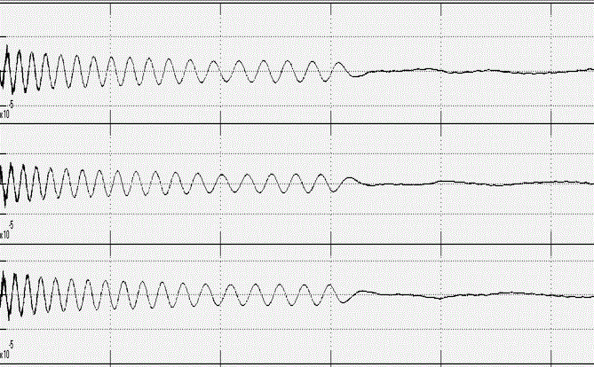
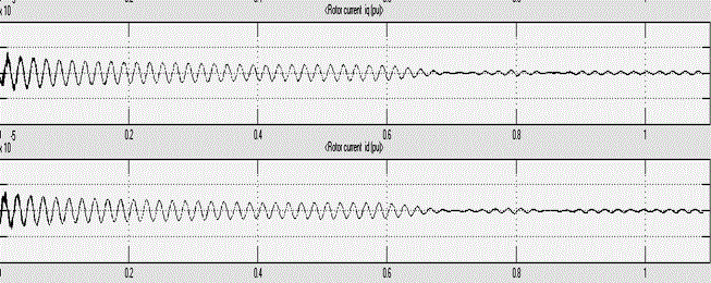
| The DFIG used 7500 VA 440V, nominal parameters. The response of doubly fed Induction Generator for rotor current in three phase quantities (ia, ib, ic) is shown in fig.5 and in d-q reference frame is shown in fig.6. |
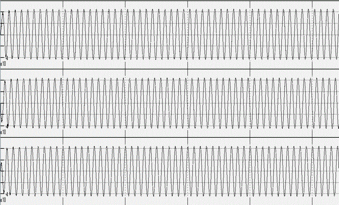
| The value of rotor current which are shown in figures 5 & 6 are injected to rotor circuit of the DFIG and hence, the flux generated by rotor circuit is controlled. As the command provide to rotor side converter by controller circuit. Similarly, the three phase stator current (Ia,Ib,Ic) is shown in fig.8 in per unit. |
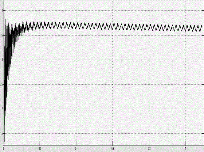
| The responses of three phase rotor current have become stable, the settling time is also reduced by using controller and the oscillations are also damped out. The electromagnetic torque is now become constant after specific marginal time. |
CONCLUSION
|
| As the different figure shown stator circuit 3 phase current (Ia,Ib,Ic) are AC and the flux produced by these current will be rotating. The rotor circuit controlled flux (which is controlled due to injecting current controlling though rotor side converter) and rotating flux of stator circuit operation of DFIG are obtained. Hence, active power flow through DFIG can also be controlled. Waveform shows the active power compensation took place and controlling of frequency through wind turbine based on DFIG has been done. |
| |
Figures at a glance
|
 |
 |
 |
 |
| Figure 1 |
Figure 2 |
Figure 3 |
Figure 4 |
 |
 |
 |
 |
| Figure 5 |
Figure 6 |
Figure 7 |
Figure 8 |
|
| |
References
|
- Abdin E.S., Xu W., “Control design and dynamic performance analysis of wind turbine induction generator unit, IEEE Trans. on Energy Conversion” Vol.15, No.1, pp. 91-96, 2000.
- Holdsword L, Wu XG, Ekanayake JB, Jenkins N., “Comoarison of Fixed Speed and Doubly Fed Induction Wind Turbine During Power Disturbance.”, IEEE Proceeding: Generation, Transmission, Distribution,Vol.8, pp. 343-352, 2003.
- Zheng X., Li L., Xu D. Platts, J., “Sliding mode MPPT control of variable speed wind power system”, Power and energy engineering conference, pp. 1-4, APPEEC 2009.
- BalasubramaniamBabypriya, Rajapalan Anita, “Modelling, Simulation And Analysis Of Doubly Fed Induction Generator For Wind Turbines”, Journal of Electrical Engineering, Vol. 60, No. 2, pp. 79–85, 2009.
- Phani Shree K.H., Jaya S.V., Kumar Ram, “Decoupled control of Active and Reactive Power of DFIG with Cascaded SPWM Converters”, International Journal of Engineering science and technology (IJEST), vol.3, pp. 64-69, 2011.
- Jang J., kim Y., and Lee D., “Active and Reactive power control of DFIG for wind energy conversion under unbalance grid voltage”, in. proc. IEEE power Electronics and Motion control Conference, vol.3, pp. 55-58, 2006
- Babu B Chhitti, Mohanty K.B., Poongothai C. “Steady State Analysis And Control Of Wind Turbine Driven Double Output Induction Generator”, 3rd International Conference on Power Electronics Systems and Applications. Vol 5, pp. 16-20, 2003.
- Salles M. B. C., Hameyer K., Cardoso J. R. and Freitas W., "Dynamic Analysis of Wind Turbines Considering New Grid Requirements,” IEEE International Conference on Electrical Machines, vol 8, pp. 26-31, 2008.
|