Keywords
|
| AT mega 328, LM35, RF Module, SIM 300 |
INTRODUCTION
|
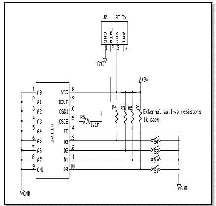
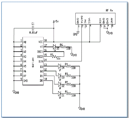
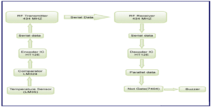
| The fire alarm circuit can be divided into four parts consisting of temperature sensor, comparator, trans receiver (RF module) and the output. A temperature sensor (LM35) is placed at a particular place whose output is given to the negative end of the comparator. LM324 is the comparator IC in the circuit. The positive end is connected to a preset, which can be varied to set the reference temperature in accordance with the sensitivity of the sensor. As long as the output of LM 35 is below the set reference voltage, the output of comparator stays high. The output from comparator is connected to the data pin (10-13) of encoder IC (HT12E). Transmission enable (TE) pin of encoder is set low while its data out (pin 17) is connected to the data (pin 2) of RF transmitter. As soon as the surrounding temperature becomes higher than the reference temperature, the comparator output goes low which leads to the transmission of a signal. The signal is received by the RF receiver, which is given to pin 14 of decoder IC (HT12D). |
| The signal received is low which is thus passed to an inverter (74LS04) and its output connected to a buzzer which then goes on. Since GSMis widely used mobile communication architecture in many countries. Thus, it demonstrates the interfacing of GSM Module with ATmega 328. It aims to familiarize with the syntax of AT Commands, their Information Response and Result Codes. Global System for Mobile (GSM) communication is the Second Generation of mobile technology. Although we are in the era of 3G and 4G but GSM has been the most successful and widespread technology in the communication sector till date. GSM technology gave birth to a new way for mobile communication. |
DESIGN OF FIRE ALARM
|
| A. RF Communication |
| The RF module operates at Radio frequency, which ranges between 30 kHz & 300 GHz. In this system, the digital data is shown as varying amplitude of carrier wave. This type of modulation is called as Amplitude Shift Keying (ASK). Radio Frequency Communication is better than Infrared Communication as: |
| • RF Signals travels large distance. |
| • RF can pass even through obstacles but IR follows Line of Sight. |
| • RF transmission is more strong and reliable in comparison with IR transmission. |
| • RF communication uses a specific frequency though other IR emitting sources distracts IR signals. |
| The module comprises of an RF Transmitter and an RF Receiver, which operates at a frequency of 434 MHz. RF transmitter receive serial data at the rate of 1-10 Kbps and transmits it wirelessly at radio frequency through its antenna connected at Pin 4. The data is received by an RF receiver, which operates at the same frequency as that of the transmitter. The RF module is used along with encoder/decoder ICs. The encoder is used for encoding parallel data, which is transmitted, and a decoder decodes it.These days RF is commonly used in communications and remote control applications. In this project RF transmitter and receiver is used in range of 80m to 100m at standard conditions like temperature, humidity etc. The data is given to the encoder IC in parallel ports. The encoder IC receives the code and converts it into the serial data before sending it to RF transmitter. The transmitter gives rise to a corresponding RF signal based on the user input. The first RF Receiver module receives the data signal in serial manner, which is converted back to parallel output by the decoder IC. |
| I. RF Transmitter & Receiver- |
| Input is given to the transmitter and transmitted via chosen channel (wireless) to receiver. The receiver module receives this incoming signal and fed to inverter whose output is connected to a buzzer, which goes on. |
| II. Encoder- |
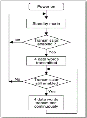
| The HT12E is an 18-pin encoder IC that has a series of CMOS LSIs. It is able to encode information that comprises of N address bits and 12N data bits. These bits are transmitted along with the header bits via RF transmission when there is trigger signal. |
| III. Decoder – |
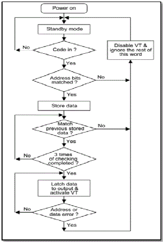
| The HT12D is also an 18-pin decoder IC which is capable of decoding information that consist of N bits of address and 12N bits of data. It is arranged to provide 8 address bits and 4 data bits and can decode 12 bits of address information. |
WORKING
|
| The HT12E-12D series of encoders and decoders transport 12 bits of data out of which 8 are address bits and 4 are data bits. |
| For both the encoder and the decoder A0 –A7 signifies address bits and D0 – D4 characterizes data bits. The Transmit Enable pin of the encoder is grounded which drives data to the transmitter. |
| The data bits are relocated in parallel mode to the input four data pins. A combinational series data bits are produced at the data output pin. This befalls at 434 MHz and hence we are not able to get any data lack. The data is then transferred to the RF Transmitter and is acknowledged by the RF receiver, which serves the decoder through the data input pin serially. This received data is then translated into parallel data bits, which can be expended for vital application. |
| B. GSM Module Interfacing with ATmega 328 |
| The output of LM 35 is fed to analog input 0 i.e. Pin No - 23. The coding is done is such a way that whenever the temperature sensor experiences the temperature above the set reference temperature it sends a SMS to the mobile no. entered in the code using Attention (AT) commands. |
| The code is written exclusively for this purpose and serial communication takes place at 9600-baud rate for which we use the following algorithm: |
| 1. Initialize the output as 0. |
| 2. In Void Setup, Start the serial communication at 9600-baud rate. |
| 3. In Void Loop, read the raw voltage from the pin 0 using analog read in-built function. |
| 4. Since, ATmega 328 has 1024 bits for 5 Volts. For 1 Volt, it’ll have 5/1024 voltage per bit. |
| 5. Sensitivity of LM 35 is 0.01 V per degree Celsius. Convert accordingly using this relation |
| 6. Using Serial print command, display it in serial monitor. |
| 7. For GSM, use AT-ATTENTION Commands for temperature greater than 65 (Set Reference Temperature). |
| 8. AT+CMGF=1 set the GSM module as text mode. |
| 9. Using AT+CMGS give the number to which text needs to be sent in international format. |
| 10. Enter your message using serial print command. |
| 11. Give necessary delay and end. |
| The GSM Module used is SIM 300 model. A GSM/GPRS module accumulates a GSM/GPRS modem with prevailing communication interfaces as RS-232 (Serial Port), USB etc., so that it can be simply interfaced with a system based on microcontroller. The power supply circuit is also fabricated in the module that can be prompted by using a proper adaptor. |
| It comprises of a set of wireless MODEM devices that are intended for communication of a computer with the GSM and GPRS network. It involves a SIM (Subscriber Identity Module) Card. They also have IMEI (International Mobile Equipment Identity) number for their identification. A GSM Module can accomplish the following tasks: |
| 1. Make, Receive, or reject a voice call |
| 2. Read, add, and search phonebook entries of the SIM. |
| 3. Receive, send or delete SMS messages in a SIM. |
| The Modem requires AT commands, for intermingling with controller by serial communication. These commands are sent by the microcontroller (RTS – Request To Send). The modem sends back a result after it receives a command in form of handshake signals that are exchanged before any serial communication (CTS – Clear To Send). Different AT commands are supported by the modem that can be sent by the microcontroller to interrelate with the cellular networks. |
COMPARISION WITH EXISTING FIRE TECHNOLOGIES
|
| Existing fire alarm technologies are composed of alarm initiating devices (smoke detectors and heat sensors), alarm notification appliances (sirens or devices that produce large noises), fire control units (sprinkler systems or fire extinguisher systems), power supplies and wirings. Fire alarm systems notify the occupants of the building or a house of a possible fire so that the occupants can either evacuate for safety or extinguish the fire before it could spread out and become incontrollable. These systems are set off automatically by smoke detectors, heat detectors. The sensors are set to detect certain levels of heat or smoke that could be a warning of fire. A loud bell guides blinking for folks who have hearing troubles; blasts are present to alert the occupants in the building. In a fire alarm system, there is always a smoke detector to detect the smoke or fire. |
| In the existing fire alarm technologies, a fire alarm system work by way of sensor, which work on smoke. They are classified as: optical detector and the ionization detector out of which the optical smoke detector senses smoke through light sensors (infrared LED). As soon as the smoke particles pass within the chamber of the optical detector, it scatters light that trigger the alarm. In the ionization detector, if the smoke particles arrive the chamber of the ionization detector it diminishes air ionization inside the chamber of the ionization detector and triggers the alarm. Another aspect of how a fire alarm works is the heat sensor or also called thermal sensor. The heat sensor monitors the temperature in a room and any abrupt rise or sudden extreme change in the temperature triggers the fire alarm. Some fire alarms have automatic diallers that dial an emergency number (fire department) in case of an emergency. |
SIMULATION RESULT
|
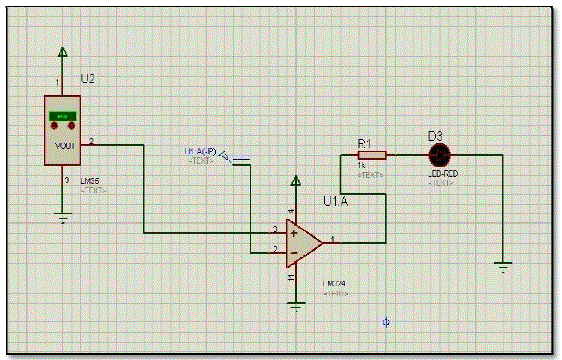
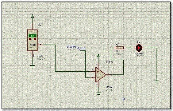
| Using Proteus Software, simulation analysis was done at a set reference temperature of 65 degree. |
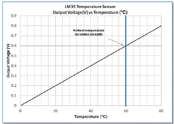
| The variation of temperature and voltage for LM 35 temeperature sensor is linear in nature. Thus, the sensitivity of this sensor is 0.01 degree per celcius. |
CONCLUSION
|
| From this project, we infer that the usage of GSM module incorporated RF communication fire alarm is an effective method to ensure a speedy response in case of a fire, and as well as balance in cost and maintenance. Using of RF communication helps in including large areas under the ambit of fire security as required in large buildings and offices at the luxury of a single monitoring station and thus eliminates the need to have various controls or monitor points. The GSM module attached serves as an immediate notifier in case of a fire to the concerned authority or fire station and thus adds a great deal to the safety measures. |
| |
Figures at a glance
|
 |
 |
 |
 |
 |
| Figure 1 |
Figure 2 |
Figure 3 |
Figure 4 |
Figure 5 |
 |
 |
 |
 |
 |
| Figure 6 |
Figure 7 |
Figure 8 |
Figure 9 |
Figure 10 |
|
| |
References
|
- RF-System-On-Package (SOP) for Wireless Communications Kyutae Lim, Stephane Pinel, Mekita Davis, Albert Sutono, Chang-Ho Lee,Deukhyoun Heo, Ade Obatoynbo, Joy Laskar, Emmanouil M. Tantzeris, Rao Tummala – IEEE Microwave Maganzine, March 2002.
- GSM-based distribution transformer monitoring system Al-Ali, A. -R.; Sch. of Eng., American Univ. of Sharjah, United Arab Emirates;Khaliq, A.; Arshad, M. Electrotechnical Conference, 2004. MELECON 2004. Proceedings of the 12th IEEE Mediterranean (Volume: 3).
- An Online Temperature Measurement System Based Wireless Communication TechnologyZhou Niancheng; Zhang Jingwei; Gan Hong Power System Technology, 2006. PowerCon 2006. International Conference on, 2006.
- A Duplex Wireless Audio Communication System- Ying, Yun; Shuguang, Dai; Ping'an, Mu; Tianfa, Su Electronic Measurement andInstruments, 2007. ICEMI '07. 8th International Conference on, 2007.
- Implementation of RF communication with TDMA algorithm in swarm robots Bhandari, S. ; Eng. Dept., Trinity Coll., Hartford, CT ; Gautam,P. Technologies for Practical Robot Applications, 2008. TePRA 2008. IEEE International Conference.
- GSM Modem-Based Mobile Auxiliary Learning System Suqun Cao; Fac. of Mech. Eng., Huaiyin Inst. of Technol., Huai''an, China -Computational Intelligence and Software Engineering, 2009. CiSE 2009. International Conference.
- RF communication data model for satellite networks by Beering, D.R. MorganFranklin Corp., West Chicago, IL, USA Tseng, S.; Hayden, J.L.; Corder, A. ; Teng Ooi ; Elwell, D. ; Grabowski, H. ; Frederic, R. ; Franks, J. ; Fish, R. ; Johnson, A.M. ; Gavin, N.E. - MilitaryCommunications Conference, 2009. MILCOM 2009. IEEE.
- GPS-GSM Integration for Enhancing Public Transportation Management Services Farooq, U. Dept. of Electr. Eng., Univ. of The Punjab,Lahore, Pakistan ul Haq, T.; Amar, M.; Asad, M.U. ; Iqbal, A. - Computer Engineering and Applications (ICCEA), 2010 Second InternationalConference on (Volume:2).
- On the Distribution of the Sum of Gamma-Gamma Variates and Applications in RF and Optical Wireless Communications byChatzidiamantis, N.D.; Karagiannidis, G.K. Communications, IEEE Transactions on, 2011.
- [10] Underwater Radio frequency Communications by Palmeiro, A.; Nautilus Oceanica, Madrid, Spain; Martin, M.; Crowther, I. ; Rhodes, M.,OCEANS, 2011 IEEE – Spain.
- General Application Research on GSM Module by Ma Yuchun; Hainan Key Lab. of Embedded Syst., Qiongzhou Univ., Sanya, China; HuangYinghong; Zhang Kun; Li Zhuang - Internet Computing & Information Services (ICICIS), 2011 International Conference.
- Multi function control system using GSM modem based SM5100B Module Mghawish, A.; Dept. of Computer. Sci., Alzaytoonah Univ. ofJordan, Amman, Jordan; AbdelQader, A.A.; Al-Jezawi, M.A.; AbuMahfouz, M. - Internet Technology And Secured Transactions, 2012International Conference.
|