Keywords
|
| Power Quality (PQ), Static Synchronous Compensator (STATCOM), Synchronous Reference Frame Theory (SRF Theory) Hysteresis Band Current Controller (HBCC), Fuzzy Logic Controller (FLC), Differential Evolution Algorithm (DE) and Total Harmonic Distortion (THD) |
INTRODUCTION
|
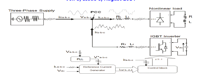
| Non linear loads are widely used in industrial, commercial, domestic applications, produces harmonics. These harmonics will affect the performance of the power system and will change the shape of the current waveform from a sine wave to non sinusoidal one. Harmonic currents produced by nonlinear loads are injected back into power distribution systems through the point of common coupling (PCC).These perturbations (harmonics) are the origin of many problems and affect electrical equipments connected to the power supply. To mitigate these harmonics shunt connected STATCOM is used. |
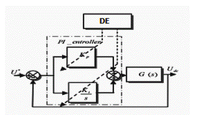
| In this work the concentration is on the identification of harmonic currents with SRF theory in time domain. Proportional plus Integral controller is used to control the loop. PI controller parameters are tuned to maintain DC capacitor voltage Constant. Here conventional PI controller is compared with Fuzzy PI controller, further PI parameters are optimized with Differential Evolution Algorithm (DE) then finally Hysteresis Band Current Controller (HBCC) is used to control the switching of Voltage Source Inverter. |
LITERATURE SURVEY
|
| Nonlinear loads appear to be prime sources of harmonic distortion in a power distribution system. So far passive shunt filters which consists of tuned LC filters/high pass filters are used to suppress the harmonics in power system. However, shunt passive filter have resonance problem, fixed compensation. To overcome the Disadvantages of passive filters FACTS controller STATCOM is used. Concept of STATCOM is proposed by Gyugyi in 1976[1]. A STATCOM is a shunt connected static var compensator whose capacitive or inductive output current can be controlled independent of the ac system voltage. STATCOM is used to improve power quality of the system by injecting compensating currents. The performance of an STATCOM mainly based on the reference current generation strategy, current control technique, power inverter topology. One of the important tasks in the STATCOM design is the maintenance of constant DC voltage across the capacitor connected to the inverter. This is necessary because there is energy loss due to conduction and switching power losses associated with the controllable switches of the inverter, which tend to reduce the value of voltage across the DC capacitor. Generally, PI controller is used to control the DC bus voltage [4]. The PI controller based approach requires precise linear mathematical model which is difficult to obtain. Also, it fails to perform satisfactorily under parameter variations, non-linearity, and load disturbances. The necessity of using intelligent tools in power quality analysis is increasing day by day to enhance power quality in the utility. Fuzzy Logic Controller (FLC) was proposed by Professor Lotfi Zadeh in 1965 has generated a great deal of Interest in various applications and has been introduced in the power electronics field [5]. The research work is further extended to the optimization of Kp, Ki parameters of PI controller using Differential Evolution Algorithm (DE) to maintain constant DC capacitor voltage. Storn and Price in 1997 introduced Differential Evolution (DE) which has proved to be an effective algorithm amongst the best known direct search approaches for nonlinear, non-differentiable objective functions. [9] |
SYSTEM CONFIGURATION
|
| A 3- φ , 415V, 50Hz supplied STATCOM is developed in MATLAB/SIMULINK using Sim power System toolbox. A. Design Parameters of STATCOM: A STATCOM consists of three phase, 6 pulse voltage source inverter. The designs for dc bus capacitor, dc bus voltage and input filter inductance are as follows (i) DC Capacitor Voltage (Vdc ref) : |
| It is desired that filter system should have at least 2 times boost in DC bus voltage with respect to the peak of phase AC voltage at the PCC mainly on the basis of reactive power compensation. |
 (1) (1) |
| (ii) DC Bus Capacitor (Vdc ) : |
| The Energy storage capability of the DC bus of the Filter should be sufficient to sustain disturbances arising due to load disturbances. The DC bus capacitance (Vdc) of the filter can be derived from the following equation: |
 (2) (2) |
| Where ΔEdc is the rate of change of energy stored in the capacitance |
| (iii) Input Filter inductance (L ) : |
| The inductances used in the active power filter smoothens the ripples from the voltage source inverter. These inductances are designed with information on the carrier signal frequency and the hysteresis bandwidth of the filter current. |
| By applying KVL at the PCC and the inverter pole point |
 (3) (3) |
| Where Vf the instantaneous value of the PWM voltage at the inverter is pole point and Vs is the instantaneous voltage At the PCC |
CONTROL STRATEGY
|
| A) SRF THEORY: |
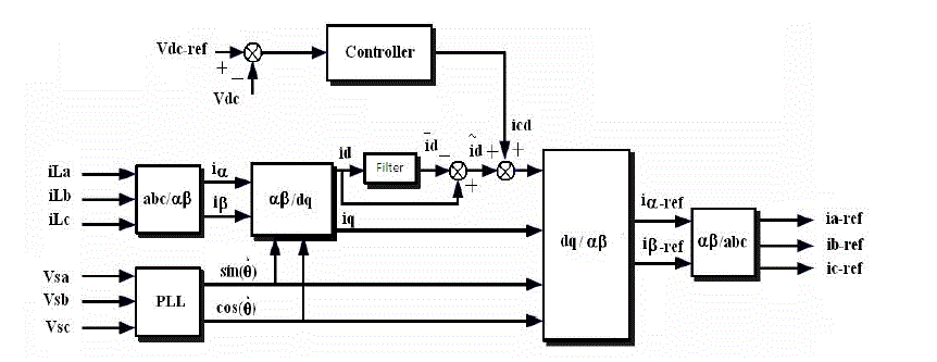
| The synchronous reference frame theory is one of the methods in time-domain based reference current generation techniques. Important characteristic of this theory is the simplicity of the calculations, which involves only algebraic calculation. The d-q transformation output signals depend on the load currents (fundamental and harmonic frequency components) and the performance of the phase locked loop. The PLL circuit is providing sinθ and cosθ for synchronization. It performs the operation in steady-state or transient state as well as for generic voltage and current waveforms. The reference frame transformation is formulated from a three-phase abc stationary system to the direct axis (d) and quadratic axis (q) rotating coordinate system [2].Park’s Transformation and Clarke’s Transformation are used to decouple the active and reactive components (4). Park’s Transformation is used to simplify the computational complexity by converting the three phase components into equivalent two phase components (5). |
| The block diagram of the synchronous reference frame controller is shown in fig 2. |
 (4) (4) |
 (5) (5) |
 (6) (6) |
When  are the DC components and AC component of the load currents on Dq frame, respectively. From equation (6), it is shown that the dq load currents consist of two terms. The high-pass filter (HPF) is used to separate the harmonic components from the dq load currents (iLd, iLq), Half of the fundamental is taken as the cut-off frequency of the high pass filter frequency. [3] are the DC components and AC component of the load currents on Dq frame, respectively. From equation (6), it is shown that the dq load currents consist of two terms. The high-pass filter (HPF) is used to separate the harmonic components from the dq load currents (iLd, iLq), Half of the fundamental is taken as the cut-off frequency of the high pass filter frequency. [3] |
 (7) (7) |
 (8) (8) |
| Finally, the harmonic components are converted back into three phase quantities by applying Reverse Park’s and Reverse Clarke’s Transformations as shown in equations (7) and (8). These signals are taken as reference signals to the hysteresis current controller to generate the gate pulses to the inverter. |
| B) PI CONTROLLER: |
| The PI controller consists of proportional term (KP) and integral term (Ki). Proportional value determines the reaction to the error the Integral determines the reaction based on the sum of recent errors. The reference currents for the control of active filter are generated according to the equation (8).The output of PI controller at the dc bus voltage of active filter is considered as the current (iloss) for meeting the injection requirements. |
 (9) (9) |
Where,  is the error between the reference (Vdc*) and sensed (Vdc) dc voltage at the nth sampling instant. KP and Ki are the proportional and the integral gains of the dc bus voltage PI controller. The placement of PI controller is shown in Fig.3 [4]. is the error between the reference (Vdc*) and sensed (Vdc) dc voltage at the nth sampling instant. KP and Ki are the proportional and the integral gains of the dc bus voltage PI controller. The placement of PI controller is shown in Fig.3 [4]. |
| C) FUZZY LOGIC CONTROLLER: |
| The concept of Fuzzy Logic Controller (FLC) was proposed by Professor Lotfi Zadeh in 1965, at first as a way of processing data by allowing partial set membership rather than crisp membership. Soon after, it was proven to be an excellent choice for many control system applications. |
| Fuzzy control is based on a logical system called fuzzy logic. It is much closer in spirit to human thinking and natural language than classical logical systems. Nowadays, fuzzy logic controller is used in almost all sectors of industry, power systems and science. One of them is the harmonic current and reactive power Compensation control [5]. |
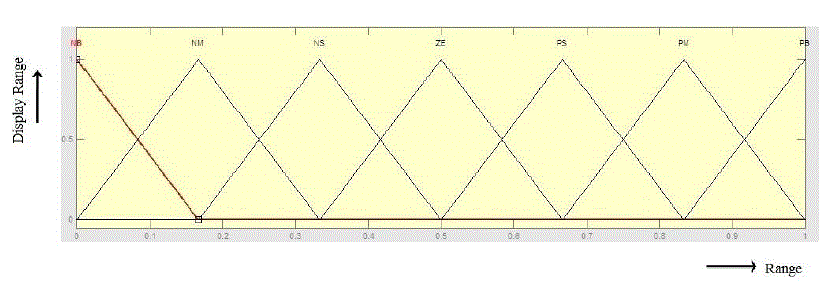
| a) Fuzzification: Just like an algebraic variable takes numbers as a value, a linguistic variable takes words or sentences as values. The set of values that it can take is called its term set. Each value in the term set is a fuzzy variable defined over a base variable. Lofti Zadeh proposed the concept of linguistic or fuzzy variables. In a control system, error between reference and output can be labeled as zero (ZE), positive small (PS), negative small (NS), positive medium (PM), negative medium (NM), positive big (PB), negative big (NB). The process of converting a numerical Variable (real number) to a linguistic variable (fuzzy number) is called Fuzzification. The membership function of a fuzzy logic control system is shown in figure 5. This figure shows two inputs the error (E), its variation (ΔE) and one output. |
| b) Defuzzification: The rules of FLC generate required output in a linguistic variable (Fuzzy Number) according to real world requirements. The choices available for Defuzzification are numerous. The conversion of a fuzzy set to a single crisp value is called Defuzzification. Finally, crisp output is obtained by using |
| Output = ΣAi* xi / Σ Ai (10) |
| c) Rule Base: The Rule base stores the linguistic control rules required by rule evaluator (decision making logic the formulation of its rule set plays a key role in improving the system performance [6][7] |
| D) HYBRID PI-FUZZY CONTROLLER: |
| The objective of the hybrid controller is to utilize the best attributes of the PI and fuzzy logic controllers to provide a controller which will produce better response than either the PI or the fuzzy controller. There are two major differences between the tracking ability of the conventional PI controller and the fuzzy logic controller. Both the PI and fuzzy controller produce reasonably good tracking for steady-state or slowly varying operating conditions. However, when there is a step change in any of the operating conditions, such as may occur in the set point or load, the PI controller tends to exhibit some overshoot or oscillations. The fuzzy controller reduces both the overshoot and extent of oscillations under the same operating conditions. Although the fuzzy controller has a slower response by itself, it reduces both the overshoot and extent of oscillations under the same operating conditions. The desire is that, by combining the two controllers, one can get the quick response of the PI controller while eliminating the overshoot possibly associated with it. [8] |
| E) HYSTERESIS BAND CURRENT TECHNIQUE: |
| The hysteresis band is used to control load currents and determine switching signals for inverters gates. Suitable stability, fast response, high accuracy, simple operation, inherent current peak limitation and load parameters variation independency make the current control methods of voltage source inverters. |
| The switching takes place when carrier signals crosses the error signal of iref and iact.a comparision of carrier signals with the error signal of iref and iact realizes the PWM switching law described below: |
| If (iact) < (ia* + hb) upper switch of a leg is OFF and lower switch is ON |
| If (iact) > (ira*+ hb) upper switch of a leg is ON and lower switch is OFF [5] |
| F) DIFFERENTIAL EVOLUTION: |
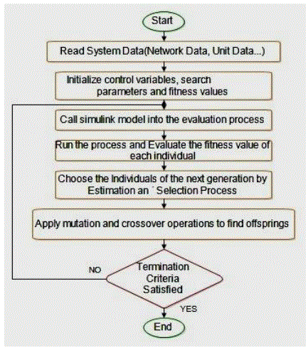
| Storm and Price in 1997 introduced Differential Evolution (DE) which has proved to be an effective algorithm amongst the best known direct search approaches for nonlinear, non-differentiable objective functions. DE algorithm is a stochastic, population-based optimization algorithm. It creates new candidates solutions by combining the individual and several other individuals of the same population. DE generates new vectors of parameter by adding the weighted difference between two population vectors to a third one. A candidate replaces the parent only if it has better fitness value. DE is an effective, fast, simple, robust, inherently parallel, and has few control parameters, needs little tuning. |
| The first step’s population initialization, kth parameter in the ith Parameter Vectors (PV’s) of the first generation can be obtained by: |
 (11) (11) |
Where  are the lower and upper bounds of the kth parameter, respectively, and rand (0, 1) is a random scalar within (0, 1). are the lower and upper bounds of the kth parameter, respectively, and rand (0, 1) is a random scalar within (0, 1). |
| Secondly the concept of mutation is carried out as shown below |
 (12) (12) |
| Where the sub scripts r1,r2, and r3 represent the randomly selected PVs such that r1≠r2 ≠r3 ≠i. s is a user-defined constant called the step size. It controls the scale of differential variation and usually selected to be in the range of 0 ≤ s ≤ 1. The main idea behind DE is a scheme for generating trial PVs. which deals the crossover action. |
 (13) (13) |
Where the superscript k indicates that the kth component of the trial PV, randi k is a random scalar so that 0 ≤ randi k ≤ 1, and Jrand is a randomly chosen integer so that 1 ≤ Jrand ≤ D. Jrand is chosen once for each vector and ensures that  obtains at least one parameter fromv Vi,G+1 . CR, the DE controlling parameter, is called crossover rate which is user-defined and usually within the range 0 < CR < 1.The best of the candidate are selected to reconstruct the new generation where the evaluation and selection is carried out at last [7-8]. In short, DE operation includes four stages as described in Fig.8. [9] obtains at least one parameter fromv Vi,G+1 . CR, the DE controlling parameter, is called crossover rate which is user-defined and usually within the range 0 < CR < 1.The best of the candidate are selected to reconstruct the new generation where the evaluation and selection is carried out at last [7-8]. In short, DE operation includes four stages as described in Fig.8. [9] |
SIMULATION RESULTS
|
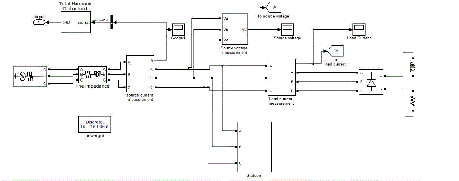
| This section describes the comparison of different controllers i.e., PI controller, fuzzy PI, PI based Differential Evolution (PI-DE) are compared and total harmonic distortion of source current is illustrated for each controller. Three phase non-linear load (Diode rectifier) is considered for simulation, SRF theory is used to estimate the reference compensating current, Matlab simulation circuit is shown in Fig.10. |
| In table.2 THD of source current for Phase A is tabulated and design parameters of the system model are given below in table.3 |
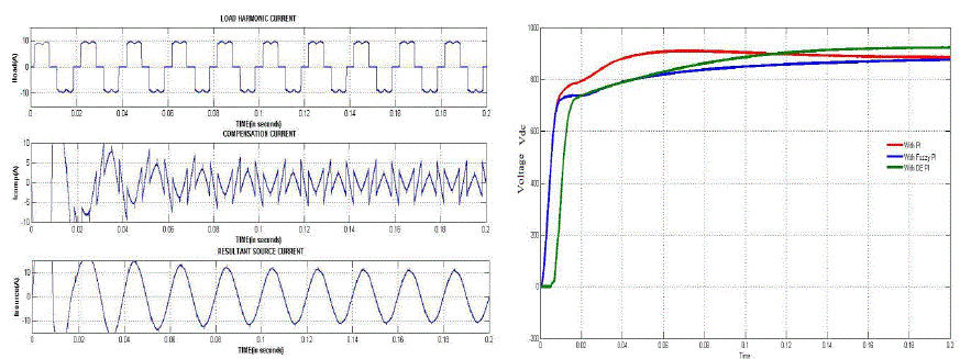
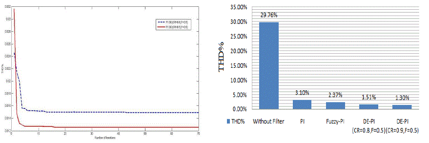
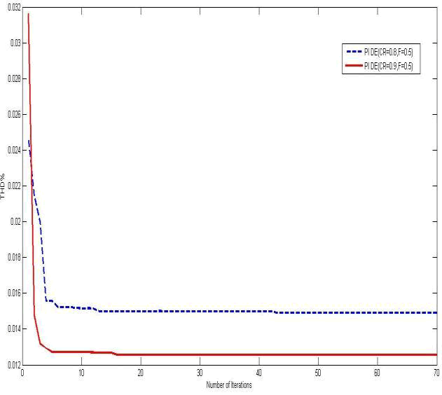
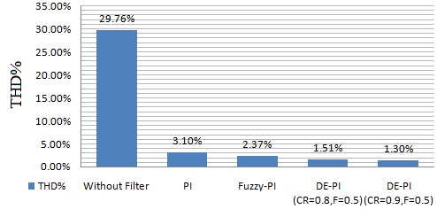
| Without Filter the illustration of THD in source current is 29.76% as shown in fig.14.With STATCOM PI controller the THD in source current is reduced to 3.10 % as shown in Fig.14.With STATCOM FUZZY-PI controller the illustration of THD in source current this is reduced to 2.37%.With STATCOM PI-DE optimized controller the illustration of THD in source current which is reduced to 1.30% making Kp and Ki ranging from (0,1), CR=0.9 and F=0.5 and Convergence of THD is shown in Fig.14. The Dc Link voltage regarding this is shown in Fig.12, Ten populations are considered for evaluation. The PI-DE optimization has been run for 70 iterations and the Convergence evaluation of simulation has been illustrated. |
CONCLUSION
|
| In this paper SRF theory is used to generate reference currents to control STATCOM which is used to compensate reactive power and harmonic currents with different types of Controllers. Comparative analysis of different controllers, i.e., conventional PI controller, fuzzy PI controller with Differential Evolution PI controller, showed that DE Optimization has been proved to be better in terms of harmonic reduction and compensating the reactive power. The dc bus voltage has been maintained constant equal to the reference voltage by all PI, Fuzzy PI, and Differential Evolution controllers. It has been found that these robust and nonlinear controls prove to be better than conventional control. SRF based STATCOM has been successfully simulated using MALAB/SIMULINK power system tool box software. |
| |
Tables at a glance
|
|
|
| |
Figures at a glance
|
 |
 |
 |
 |
 |
| Figure 1 |
Figure 2 |
Figure 3 |
Figure 4 |
Figure 5 |
 |
 |
 |
 |
 |
| Figure 6 |
Figure 7 |
Figure 8 |
Figure 9 |
Figure 10 |
 |
 |
 |
 |
| Figure 11 |
Figure 12 |
Figure 13 |
Figure 14 |
|
| |
References
|
- N.G.Hingorani & L.Gyugyi, Understanding FACTS: Concepts and Technology of Flexible AC Transmission Systems IEEE Press, 1999.
- Jeeva S. Pridaaa, P Tamizharasi and J. Baskaran, ‘Implementation of Synchronous Reference Frame Strategy based Shunt Active Filter’ IEEE.
- 2011.
- María Isabel Milanés Montero, Member, IEEE, Enrique Romero Cadaval, Member, IEEE, and Fermín Barrero González Member, ‘Comparison of Control Strategies for Shunt Active Power Filters in Three-Phase Four-Wire Systems’ IEEE TRANSACTIONS ON POWER ELECTRONICS VOL.22, NO. 1., IEEE JANUARY 2007
- Karuppanan P and KamalaKanta Mahapatra ‘PLL with PI, PID and Fuzzy Logic Controllers based Shunt Active Power Line Conditioners’IEEE PEDES- International Conference on Power Electronics, Drives and Energy Systems-, at IIT Delhi 2010.
- R. Belaidia, A. Haddouchea, H. Guendouza ‘Fuzzy Logic Controller Based Three-Phase Shunt Active Power Filter for Compensating Harmonics and Reactive Power under Unbalanced Mains Voltages’ Elsevier Energy Procedia 18 560-70., 2012.
- Karuppanan P and KamalaKanta Mahapatra “Fuzzy Logic Controlled Active Power Line Conditioners For Power quality improvementsInternational Conference on Advances in Energy Conversion Technologies, pp.177-181., ICAECT2010.
- Karuppanan P, Kamala Kanta Mahapatra ‘PI with Fuzzy Logic Controller based APLC for compensating harmonic and reactive power’ Proc. Of Int. Conf. on Control, Communication and Power Engineering pp.45-49., 2010.
- Dhanya K Panicker, Ms. Remya Mol Hybrid PI-Fuzzy Controller for Brushless DC motor speed control IOSR Journal of Electrical andElectronics Engineering (IOSR-JEEE) e-ISSN: 2278-1676, p-ISSN: 2320-3331, Volume 8, Issue 6, PP 33-43,NOV-DEC2013.
- Storn R, price k (1997) Differential Evolution - a simple and special heuristic for global optimization over continuous spaces. J Global Optim11:341-359.,1997.
|