Keywords
|
| HVAC, auxiliary power, efficiency, steam cycle |
INTRODUCTION
|
| A thermal power plant or TPP can be roughly categorized into 3 distinct areas – boiler turbine generation or BTG , balance of plant or BOP and switchyard . The four basic cycles in the BTG include Steam cycle , Fuel and Ash cycle , Air and draught cycle and Feed water and cooling water cycle . The BOP at Indiabulls power Amravati unit 1 consists of DM water plant , IDCT ( induced draught cooling tower) , CHP ( coal handling plant ) , AHP ( ash handling plant ) hydrogen generation plant and reservoir system . Other miscellaneous areas of the plant include plant township and ash disposal area . The major energy saving and methods to improve efficiency have been categorized cycle wise as well as area wise . |
RELATED WORK
|
| Some literary survey was done prior to writing this paper and literary citations as well as theoretical support for some of the findings has been supplemented by the works of Mr. Xu Lian (University of Nebraska) ; Mr. M. Jacob and G.D. Andreescu All the three mentioned author’s works on control systems in boilers was looked into . Fly ash data was cited from. The report on fly ash utilization by Central Electricity Authority , Government of India . Technical manuals of corporations ABB and ALSTOM were also referred to and are cited. |
BACKGROUND
|
| In light of the rapidly increasing power consumption , there is an increasing and earnest demand for maximum energy conservation and increasing the efficiency for thermal power plants . A lot of methods have been earlier propounded but rarely implemented due to lack of insight or unfeasibility in implementation . This paper presents some ingenious and tested methods for saving energy that are fly ash utilization , fuel switching , improved bowl mill design , condenser tube cleaning , replacement of BFP cartridges , using three element mode of operation , using auto converters and VAMs . All the mentioned methods have been theoretically as well as technically explained . The technical analysis and observations are presented and savings have been approximated for each method via applicable formulas . This paper draws inspiration from several references , which have been mentioned in the end . |
SCOPE OF RESEARCH AND PROPOSED METHODOLOGY
|
IV.1 Fly ash utilization
|
| According to fly ash utilization data mentioned in the report of Central Electric Authority of India , it has been made mandatory that up to 60 percent fly ash should be utilized in the TPP during the first two years of commissioning . Unfortunately the scenario of fly ash optimization is very recalcitrant in the power sector today . However ,some of the ingenious methods for fly ash utilization include manufacturing Portland cement ( FAPPC ) ,manufacturing clay fly ash bricks , aerated concrete blocks , ready mix concrete , mortar and other building materials . The use of fly ash from agricultural point of view is also beneficial . Fly ash should be used for building and construction purposes inside the plant , for example a whole township could be set up demonstrating the use and durability of fly ash bricks and FAPPC. |
IV.II Increasing efficiency in steam circuit by fuel switching
|
| Energy conservation can be achieved at fuel oil handling plant in terms of steam conservation or electrical energy conservation . Fuel oil system is an important part of a coal based thermal power station, in the absence of which the plant cannot take off from starting condition . A solution to the rising costs of oil and increase in efficiency can be provide by fuel switching from HFO to LDO . |
| HFO is highly viscous oil, which requires heating to reduce the viscosity up to15 CST to make it suitable for combustion in the Boiler. Since the HFO is under constant circulation between the boiler and the fuel oil handling plant, which always remains at some distance from Boiler, steam tracing lines are used for the heating purpose. The heating medium being steam, the loss in steam energy and condensate through steam traps are high. Looking at the reliability, availability and history of oil consumption during the past few years at the plant , it is advisable to use LDO . The core advantages of using LDO is less consumption of steam due to absence of stream tracing of LDO lines , and no atomizing , unlike HFO . So , the use of LDO should only be restricted for initial firing and subsequently changing over to HFO. |
Technical & Financial Analysis Made:-
|
| Ready steam consumption |
| Steam consumed due to condensation in atomizing header = 9.44 T/day (approx.) |
| Steam consumed due to condensation in steam tracing line= 6.2 T/day (approx.) |
| Daily consumption |
| Extra steam is consumed during oil firing when raising temperature of oil - 107 kg/ kL |
| The average HFO consumption in the previous year was - 152 kL |
| Steam consumed for heating of oil - 16.88 T |
| Total steam consumption per day 9.44+6.2+6.2= 21.84 T/day |
| Total steam consumption per year -21.84 * 365+ 16.88 = 7988.48t (approx.) |
| If Boiler efficiency =84%, |
| Then total heat loss due to steam consumption=692*7988.48*1000 = 5528028160 kcal |
| Now , the Calorific value of coal = 4259 kcal/kg |
| Annual Coal quantity in Tonnes required to produce above steam = (5528028160/ (0.84 *4259*1000)) =1545.19 T. |
| Coal cost = 1545 T * 2200 Rs/T (Delivered Price) = Rs33.99 Lakh . |
| Hence , there is direct saving of 1545 Tonnes of coal per Annum or Rs 34 Lakh . |
IV.III Improved design of bowl mills
|
| An ingenious improvement in the bowl mills can be to use Hi-Chrome material instead of Ni-Hard IV for grinding rolls and bull ring segment . This will improve the mill availability from 2500 – 3000 hr to 5000hr synchronizing with boiler annual overhauls and also eliminates fuel oil support due to mill outage . |
| Typical savings for a 275 MW unit can be estimated to be Rs 100000 per year . |
IV.IV Regular condenser tube cleaning
|
| Reservoir water source used for cooling causes different tube fouling problems that affect heat transfer and life expectancy of Condenser Tubing in Power Stations. Hence we can employ Bullet Cleaning as an effective and efficient way of cleaning condenser tubes. Spring loaded bullets are shot through the condenser tubes .The bullets moving through the tube from one end to the other scrape off the deposits and corrosion scales , resulting in a clean inside surface for the tube, ideal for proper running . These cleaners can be used and cleaned over and over again . |
Observations :-
|
| During Unit Shutdown condenser tube cleaning was done by above method. The contribution in condenser vacuum due to tube cleaning is 6.8 mm Hg, and gain in Heat rate is 6.8 Kcal/kWh. |
Technical and financial analysis :
|
 |
| Impact of Implementation:- It is summarized in the following table |
IV.V Timely replacement of BFP cartridges
|
| The BFP , or boiler feed pump is a very critical part of the boiler system . It regulates the amount of feed water going into the boiler drum and is part of a complex control system which involves controlling of the throttle valves and regulating the water supply based on the pre existent water and steam levels in the drum . Thus it is often observed that BFP takes a lot of power However , if BFP takes higher power , chances of interstage leakage in the recirculation process happen . Therefore , it should be observed as well as checked regularly and the BFP cartridge should be inspected thoroughly on a regular basis . If the need arises , it should changed for better efficiency and less power consumption . |
Impact of Implementation
|
| After replacing the catridge the current drawn by current reduced by 60 Amp. |
| Power saved per day= 1.66*6.6*60*.84*24= 13,252 KWH |
| Power saved per year= 4837,117.82 KWH |
| Saving of cost= 4837,117.82*3.4= Rs16829515 |
IV.VI Using three element mode of operation in BFP operation
|
| BFP operation involves controlling the drum level in two modes – DP mode and the Three element mode . Although the DP mode provides more robust control of the throttle valve , throttling losses do occur . Three element mode reduces these throttling losses by measuring the steam level , steam rate flow as well as the water level simultaneously , thereby resulting in a lesser loss of pressure and hence lesser demand . Pressure drop across the throttle valve can be optimized more efficiently using this method of control . |
Technical and financial analysis :
|
| Energy Saving potential in throttled FRS valve is given below which clearly indicates pump power loss can be optimized by minimizing pressure drop across the valve. |
 |
| DP optimization in DP mode gives no substantial energy saving due to controlling action of FRS valve. Further pressure drop reduction is only possible in three element mode scoop operation where FRS valve is kept fully open. |
 |
| In 275 MW capacity unit having overall efficiency of 40 % and for pump power= 7 MW, DP =7.5 kg/cm2, Total pr. Developed by pump = 180 kg/cm2, Energy saving potential & Calculated pump loss is given below which are unusually high figure. |
| Energy saving potential =29 % |
| Calculated pump loss = 1.834 % of Boiler Heat I/P |
| As flow control by throttling in case of high power pump like BFP is inefficient, flow control by speed regulation by means of BFP scoop is adopted BFP scoop operation was successfully tested in three element mode for each BFP. Pressure drop across FRS valve is observed to be3.5 kg/cm2 in valve full open condition. |
| Ampere saving achievement is given below : |
| BFP hydraulic coupling’s response time and subsequent change in drum level shows that drum level control directly through BFP scoop operation in three element mode variation is quite feasible especially under steady operating condition |
IV.VII Use of VFD and Converters for lesser loads
|
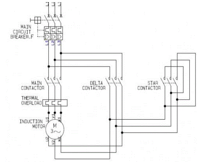
| VFD or variable frequency drives are a very useful and cost saving measure for underloaded motors . VFds can also be applied to the BFP and ID fan motors . Another practical aspect can be use of auto star / delta converters for underloaded motors . The star delta starter starts the motor in star to reduce the high starting current , and reconnects the motor in delta after the motor reaches about 80 percent of its rated speed . |
| However , it has been well observed and documented that for loads approximately less than 50 percent of the full load , using star connection is more suitable . This is so because operating in the star mode leads to voltage reduction of root 3 per phase. Motor output falls to 1/3 of the value in the delta mode, but performance characteristics as a function of load remain unchanged. Thus full load in star mode operation gives higher efficiency and power factor than partial load operation in delta mode. |
| During the study the motor (rated motor is 18 kW) was measured and monitored for the loading and other electrical parameters. The details were : |
| In view of under loading of the motor, it was suggested to operate the motor in star mode. The plant personnel immediately implemented the measure by converting the delta connection to star mode. The motor electrical parameters after star mode conversion are: |
| Figure 1.1 shows a relatively simple and yet highly efficient connections of a star delta autoconverter . It consists of two switches in a parallel connected fashion , which are responsible for the mode change between delta and star winding connections |
IV.VIII Use of vapor absorption machines (VAMs) for indoor cooling purposes
|
| Presently at most the thermal power projects in India , traditional vapor compression machines are used for cooling purposes The vapor-compression uses a circulating liquid refrigerant as the medium which absorbs and removes heat from the space to be cooled and subsequently rejects that heat elsewhere . However the major disadvantages of this system is that it consumes a lot of electricity and many refrigerants still use HCFC gases as freons and hence contribute to global warming . |
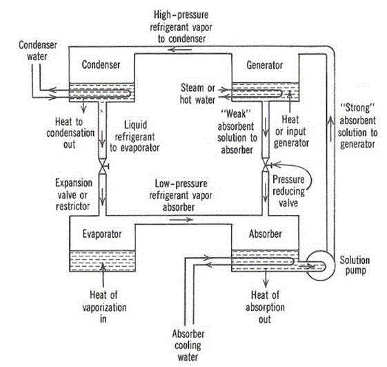
| A sensible solution to this can be the use of vapor absorption machines . An absorption refrigerator is a refrigerator that uses a heat source (e.g., solar energy, a fossil-fueled flame, waste heat from factories, or district heating systems) which provides the energy needed to drive the cooling process. The main saving principle in this is that this principle can also be used to air-condition buildings using the waste heat from the turbine and steam generation process . |
| Figure 1.2 explains the concept diagram behind vapor absorption process .Its usefulness in thermal power plants evolve from the fact that it can use the waste heat from the steam to run the air conditioning units in the entire plant . |
SIMULATION
|
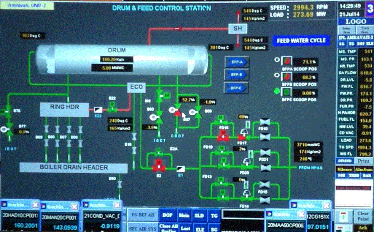
| Simulation pertaining to one method - controlling the drum in three element method was done and the digitalized monitoring and control of boiler drum was continuously done from the MCR or main control room . The software used in MCR is a heavily modified version of SCADA . The following simulations were done : |
| In figure 1.3 , the digitalized control and monitoring of all the boiler drum feed water cycle systems can be seen . The three pumps in the upper left are the symbol of the three element control mode . The 3 element mode can be switched on from here |
| In figure 1.4 , the digitalized drum and feed control station are shown . Continuous monitoring of the boiler drain header as well as the boiler drum are done and pressure sensors relay the continuous time information on the display screen . |
RESULTS
|
| From the above conducted methods , it was thus documented that a marked improvement in power consumption savings was observed . All the documentable methods and their saving potential observations has been summarized as follows : |
| 1.) FLY ASH UTILIZATION - mentioned methods promise upto 60 percent of utilization |
| 2.) FUEL SWITCHING – reduction in coal consumption by 1545 tonnes per annum |
| 3.) CONDENSER TUBE CLEANING – reduction in coal consumption by 360 tonnes per annum |
| 4.) REPLACEMENT OF BFP CARTRIDGES – upto 13,252 KWH of power saved per day |
| 5.) THREE ELEMENT MODE OF OPERATION – power savings per hour range from 40 – 130 KW per hour |
| 6.) CONVERTERS FOR LESSER LOADS – power demand goes down by 4.13 Kva , improved power factor |
CONCLUSION
|
| A marked improvement in energy conservation and increase in overall efficiency of the plant can be observed when the above points are implemented successfully at Indiabulls power Amravati Unit 1 , helping drive the cost of generation significantly lower and improving the overall economics of power generation . The above can also be a role model for the commissioned as well as upcoming new thermal projects throughout India |
ACKNOWLEDGEMENTS
|
| We are highly grateful to INDIABULLS POWER Pvt Ltd for letting us conduct a thorough research and survey of the plant and giving us the opportunity to come with cost efficient energy saving methods . We would also like to thank them for letting us use and inspect the various plant areas and equipments , in their Amravati Power Plant (Unit 1) for our research purposes . A special mention and sincere thanks would also like to be given to the entire electrical team at Indiabulls power , Amravati who cooperated with us and helped us throughout . |
| |
Tables at a glance
|
 |
 |
 |
 |
| Table 1.1 |
Table 1.2 |
Table 1.3 |
Table 1.4 |
|
| |
Figures at a glance
|
 |
 |
 |
 |
| Figure 1 |
Figure 2 |
Figure 3 |
Figure 4 |
|
| |
References
|
- INDIABULLS POWER Pvt Ltd , Amravati unit.
- Operation and maintenance manual, ALSTOM corporation ltd. Released in 2013.
- Invensys I/A Series hardware product specifications for boiler controller , dong fang electric corporation ltd. Released on 2012.
- M. Jacob, G.-D. Andreescu, Drum-boiler control system employing shrink and swell effect remission in thermal power plants, Proc. 2011 3rd International Congress on Ultra Modern Telecommunications and Control Systems and worksho
- -ps (ICUMT), Budapest, Hungary, ISSN: 2157-0221, ISBN: 978-1-4577-0682-0, pp. 1-8, Oct. 2011.
- Technology information , forecasting and assessment council report , Department of Science and Technology.
- Government of India
- Report on Fly ash generation and at coal based thermal power plants and its utilization in the country for years 2012-
- 2013 , Central Electricity Authority , Government of India . Published January 2014.
- XuLian (University of Nebraska-Lincoln), Optimized control strategies for a typical water loop heat pump system , IEEE power electronics vol 9 , 2012
- Drum level control systems in process industries (Application Guide ) , ABB Power . Published 2014
|