FACTS (Flexible AC Transmission Systems) means a family of controllers and devices for increase the use and flexibility of power systems. A FACTS controller is a power electronics-based system or other static equipment that provides control of one or more ac transmission parameters”. In this paper, a FIVE BUS SYSTEM is analyzed. . This paper will treat benefits of PST (phase shift transformer)-OLTC (on-load tap changer) installed in power systems such as control of power transmission capability. This paper also includes the main barriers of power system stability and transmission structure. It includes usage of OLTC/PST for the removal of power congestion.
Keywords |
| FACTS, PST, OLTC |
INTRODUCTION |
| Power system stability is the ability of the system, for a given initial operating condition, to regain a normal state of
equilibrium after being subjected to a disturbance. Stability is a condition of equilibrium between opposing forces;
instability results when a disturbance leads to a sustained imbalance between the opposing forces. The power system is
a highly nonlinear system that operates in a constantly changing environment; loads, generator outputs, topology, and
key operating parameters change continually[1],[2]. |
| When subjected to a transient disturbance, the stability of the system depends on the nature of the disturbance as well
as the initial operating condition. The disturbance may be small or large. Small disturbances in the form of load
changes occur continually, and the system adjusts to the changing conditions. The system must be able to operate
satisfactorily under these conditions and successfully meet the load demand [3],[4],[5]. It must also be able to survive
numerous disturbances of a severe nature, such as a short-circuit on a transmission line or loss of a large generator. |
POWER CONJESTION |
| The power congestion known as the limitations to how much power can be transferred across a transmission interfaces,
and further that there is an incentive to actually desire to transfer more power. The old approach to correct congestion
lies in reinforcing the system with additional transmission capacity (eg adding overhead lines). Although easy to
perform, this approach is complex and time consuming. It is becoming increasingly difficult to obtain the permits to
building new transmission corridors, or even expand existing ones. This can be done by installing controllable devices
in the transmission system, such as FACTS (Flexible AC Transmission System) devices, possibly supplemented with
advanced information gathering systems, avoids the need for such investments by providing more flexibility and
control.[4],[5]. Although, in general terms, the concept is commonly accepted, the application of these measures
involves a number of challenges. |
FACTS CONTROLLERS |
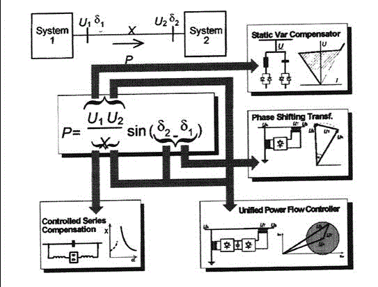
| The working of FACTS devices are explained in Fig. 1 which shows a schematic diagram of an AC interconnection
between two systems. The active power transmitted between the systems is defined by the given equation present in
fig1 where U1 and U2 are the voltages at both ends of the transmission, X is the equivalent impedance of the
transmission, and $1 -$2 is the phase angle difference between both system.From the equation in the figure given below
it is evident that the transmitted power is influenced by three parameters: voltage, impedance, and voltage angle
difference. These parameters can be very largely influenced by FACTS devices, as shown in the figure, and also
influence power flow.[6] |
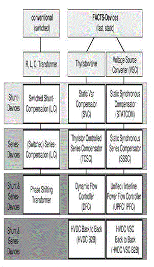
| In fig. 2, it shows a list of FACTS controllers which have been realized or are still under development [7]. They can be
used for load flow control, voltage control and stability improvement in transmission systems as well as for additional
special applications. The advantage of FACTS is that different new members of the FACTS family can be created by
combining a variety of different equipment.[8],[9]. |
TEST SYSTEM |
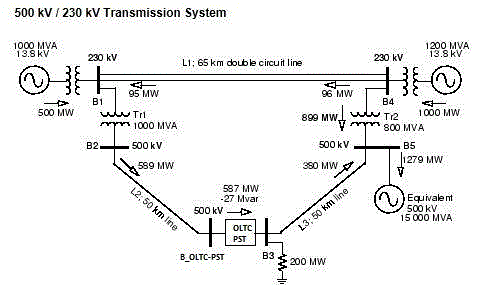
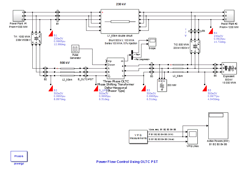
| The simulink model of the power system is shown in 500 kV / 230 kV transmission system power transfer between
two voltage with PST. |
| In fig 3, it shows the system is connected in a loop configuration. It consists of five buses (B1 to B5) which are
interconnected by three transmission lines (L1, L2, L3) and two 500 kV/230 kV transformer banks Tr1 and Tr2. There
are two power plants located on the 230 kV system that generate a total of 1500 MW which is transmitted to a 500 kV,
15000 MVA equivalent and to a 200 MW load connected at bus B3. |
| These plant models include a speed regulator, an excitation system and a power system stabilizer (PSS). The load flow
indicates that most of the power generated by plant #2 is transmitted through the 800 MVA transformer bank (899 MW
out of 1000 MW) and that 96 MW is circulating in the loop. Transformer Tr2 is therefore overloaded by 99 MVA.
Thus, a PST with an on load tap changer (OLTC) is applied to control the power flow on the power system. The
number of taps is set to 20, thus, the phase shift resolution is approximately 60/20 = 3 degrees per step. The tap position
is controlled by sending pulses to either the Up input or the Down input. In this case, as we need to increase phase shift
from zero toward positive values, we have to send pulses to the Down input and modify the following period and pulse
width (% of period) parameters. A better resolution in phase angle and power steps can be achieved by increasing the
number of taps in the OLTC. The discrete variation of phase angle produces overshoots and slight oscillations in active
power. These power oscillations which are typical inter area electromechanical oscillations of machines in power plants
1 and 2 are quickly damped by the power system stabilizers (PSSs) connected on the excitation systems. |
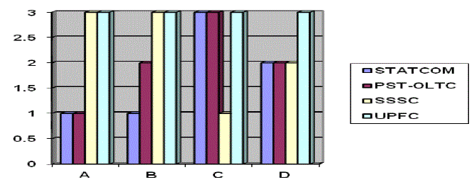
| In the fig 4, it shows comparison of different FACTS Controllers based on these properties:
A- Transient stability B-Load Flow Control C-Voltage Control D-Oscillation Damping. |
| In fig.5, it shows the Simulink model of Power flow control using OLTC-PST. |
SIMULATION RESULTS |
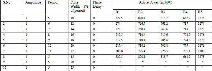 |
| Simulation table |
CONCLUSION |
| This paper presents the application of OLTC-PST, to control active power by regulating the voltage phase angle
difference between two nodes of the system. can be eliminated. The device used is free from Power Electronic devices
which mean it is free from any complexities, is very cheap and has various benefits. It gives a powerful method for
congestion relief in power system. A brief review of the device applications to control the active power and relief
congestion has been presented. Overloading of lines and loop-flows in Meshed Systems and in parallel line
configurations has been presented in very simple manner. |
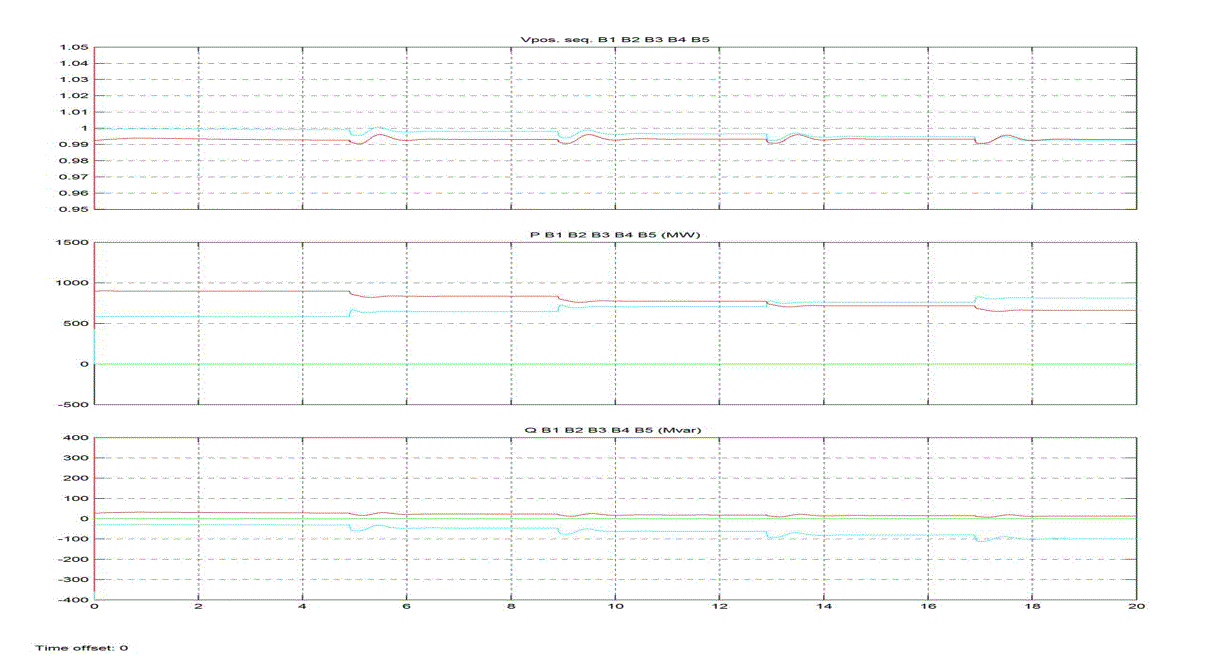
| In fig 6, it shows the resultant waveforms for different buses as per the observations obtained after running the
Simulink diagram. |
| |
Figures at a glance |
 |
 |
 |
| Figure 1 |
Figure 2 |
Figure 3 |
 |
 |
 |
| Figure 4 |
Figure 5 |
Figure 6 |
|
| |
References |
- A. E. Hammad, "Analysis of Power System Stability Enhancement by Static VAR Compensators," IEEE Trans. PWRS, Vol. 1, No. 4, 1986,pp. 222-227.
- S.M. Bamasak and M. AAbido, âÃâ¬ÃÅAssessment Study Of Shunt Facts-Based Controllers Effectiveness On Power System Stability Enhancement,âÃâ¬Ã 39th UPEC Proceedings, Vol. 1, pp 65-71, Sept 2004.
- Q P. Kundur, Power System Stability and Control. New York: McGraw-Hill, Inc., 1993.
- C. W. Taylor, Power System Voltage Stability. New York: McGraw-Hill, Inc., 1994.IEEE Guide for synchronous generator modelling practices in stability analyses, IEEE Standard 1110-1991.
- Anderson P., Fouad A., Power system control and stability, Revised Printing, IEEE Press, ISBN 0-7803-1029-2, 1994
- N.G. Hingorani, L. Gyugyi, Understanding FACTS, Concepts and Technology of Flexible AC Transmission systems, IEEE Press 2000..
- Machowski J., Bialek J., Bumby J., Power system dynamics and stability,John Wiley & Sons, ISBN 0471 97174 X (PPC), 1997.
- John J. Paserba, Fellow, IEEE, âÃâ¬ÃÅHow FACTS Controllers Benefit AC Transmission SystemsâÃâ¬Ã IEEE Transactions on Power Delivery,Vol, No 1 pages 949-957,2003.
- Y. H. Song and A. T. Johns, Flexible AC Transmission System (FACTS), IEE Power and Energy Series 30, 1999.
- Avramovic B., Fink L., âÃâ¬ÃÅEnergy management systems and control of FACTS,âÃâ¬Ã Electrical Power & Energy Systems, vol. 17, no. 3, June 1995,pp. 195-198.
- AbhishekGandhar, BalwinderSingh ,RintuKhanna âÃâ¬ÃÅImpacts of FACTS technology-A state of Art Review,âÃâ¬Ã Ã¢Ãâ¬ÃÅInternational Journal of Innovative Technology and Exploring Engineering (IJITEE)âÃâ¬ÃÂ,ISSN: 2278-3075, Volume-1, Issue-4, 28-31,September 2012.
- Edris A., âÃâ¬ÃÅFACTS technology development: an update,âÃâ¬Ã IEEE PowerEngineering Review, vol. 20, no. 3, March 2000, pp. 4-9.
|