Keywords |
| DC motor, IP network, time delay, PID controller, partial model matching method |
INTRODUCTION |
| Recently, many applications using the Internet have been developed in various fields. As one of the applications, the development of Internet Protocol (IP) network-based control systems gains more attention (e.g., [1], [2]). |
| Because the cost of hardware like hubs, routers, network interface cards, etc. is lower, it has been easy to construct IP network-based control systems connected among actuators, sensors and controllers over the networks. However, the control performance is degraded due to varying time delays such as constant time delay and its jitter over the network. Therefore, schemes to overcome the issue are required. A simple scheme is to tune a proportional-integral-derivative (PID) or PI controller properly and automatically according to network conditions. For example, [1] has proposed a scheme that auto-tunes a PI controller. Specifically, this scheme is as follows. It is assumed that varying time delays behave like exponential distributions, and the varying delays are characterised. Then the PI controller is tuned automatically according to the present delays, where the PI parameters are decided such as minimizing an evaluation function with respect to each delay beforehand. However, task for the tuning is often much time-consuming one. |
| In this paper, another scheme that auto-tunes PID controllers according to varying time delays is proposed. The proposed scheme is that first the PID controller is tuned using a partial model matching method by Kitamori [3], which can automatically choose the PID parameters according to time delays, and then the integral parameter is re-tuned with respect to its jitter. The advantage using the matching method is that proper PID parameters are automatically obtained if the transfer function of the plant model is known. That is, acquiring the value of parameters tuned according to each time delay in advance is not needed. However, the tuning method is still insufficient against jitter. Hence, to overcome the jitter issue, the relationship between the minimal time of varying time delays and the rise time of the step response are examined, where the responses are obtained by control experiment after tuning the controller based on the matching method according to each time delay. Then, based on the relationship to characterize the jitter, a method that re-tunes the integral parameter is developed. Thus, the author proposes an auto-tuning scheme including these two methods. |
| Finally, an IP network-based speed control system of an actual small DC motor, which is chosen because of a typical servomotor having a simple structure, is constructed, and after applying the proposed scheme, speed control experiments are carried out. From the step responses obtained by the experiments, it is confirmed whether the proposed scheme is effective against IP networks with varying time delays. |
IP NETWORK-BASED CONTROL SYSTEM |
| Fig. 1 shows an IP network-based speed control system for a small DC motor. The rated voltage, current, power and
speed of an actual small DC motor (Sanyo Denki R301T-011) are 24V, 1.25A, 11W and 3000min-1 respectively. The
motor is with an inertial load with 2.5 105 kg m2.V(s), r(s), m(s) and e(s) are an applied voltage [V] to the motor,
a reference speed [min-1], a rotor speed [min-1], and the error between the reference and the rotor speed, i.e., e(s) =
r(s) m(s), respectively. Gm(s) is the transfer function of the DC motor. A PID controller GPID(s) is denoted as |
 |
| where KP, KI and KD are the proportional, integral and derivative parameters respectively. In actual experiments
described in later section, the derivative term uses not only KDs, but also KDs/(1+TDs), where and TD=KD/KP.
Both sampling time of each computer to operate the controller and the plant in the figure are 0.001s = 1 ms. Each time
delay of signals of V(s) and m(s) through the IP network is expressed as L1 [s] and L2 [s] respectively. However,
because L1 and L2 are fluctuated due to network traffic conditions, the delays cannot be dealt with as a (constant) dead
time in conventional control theory. Hence, in the figure, note that their varying time delays are formally expressed as
eL1s and eL2s. |
| In this system, the behavior of IP networks between the controller and the plant is emulated by a PC router on which
a Linux network emulator netem [5] is installed. Netem can emulate time delays (as mean [ms]), its jitter (as standard
deviation [ms]) and distribution (e.g., normal distribution) of varying time delays. A communication protocol used on
the network is User Datagram Protocol (UDP). Packets including a control signal may be lost since UDP has no
reception confirmation. Moreover a packet sent from the controller earlier may receive at the plant later or vice versa.
This issue is packet disorder [6]. In this paper, if a packet has not been received within a sampling period or disorder
has occurred, then the receiver employs the latest one obtained at the preceding period. Moreover, it is assumed that the
influence of the packets loss can be negligible. |
AN AUTO-TUNING OF THE SYSTEM WITH A DEAD TIME BY PARTIAL MODEL MATCHING METHOD |
| The partial model matching method by Kitamori [3] can decide PID parameters automatically such that the closed
loop transfer function of a provided system including the controller coincides with a function of a reference model,
where the response of the reference model is the one that a designer wants to design. In this section, it is explained how
the method is applied to a system with a “constant” time delay, i.e., a dead time L as shown in the upper figure of Fig. 2,
not “varying” time delays as in Fig. 1. This method with a dead time is provided as follows [4]. |
| APID controller GPID(s) is denoted as (1). First, the transfer function of the DC motor model in the plant is described
as Gm(s) = 1/(g0+g1s+g2s2), and Gmd(s), which is the function of the motor with a dead time L, is |
 |
| Let g0 = 4.807 103, g1 = 6.346 104 and g2 = 7.232 108, whose parameters of the motor are empirically derived
beforehand. Moreover, let |
 |
| Now, in (2), the Maclaurin series expansion of eLs is done, i.e., eLs = 1 + Ls + L2s22! + L3s33! +…. Then, since (2) is
equivalent to (3), the following relations (4) are obtained, |
 |
| Second, a reference model transfer function W(s) is introduced as |
 |
| where let {0, 1, 2, 3, 4} = {1, 1, 17/40, 39/400, 109/7599} [4] and is a time scaling parameter. The response of
W(s) in the system shown in the lower figure of Fig. 2 means the desirable one that a designer wants to design in the
actual system illustrated in the upper figure. Then PID parameters KP, KI and KD, are determined such that the coefficient
of each term from low to high order in s of the closed-loop function G(s) = GPID(s)Gp(s)/{1+GPID(s)Gp(s)} matches that
of W(s), as illustrated in Fig.2. That is, these parameters are done as following formulas: |
 |
| where is a minimum positive solution, and satisfies the following equation |
 |
THE PROPOSED AUTO-TUNING SCHEME ACCORDING TO VARYING TIME DELAYS |
| The auto-tuning method using the partial model matching method described in the previous section is discussed in
the case that a time delay in the system is constant as shown in Fig. 2. However, because time delays vary over IP
networks as shown in Fig. 1, a tuning scheme according to fluctuating delays, i.e., the jitter, needs to be developed. |
| A. The Relationship Between Minimum Delay Time and Rise Time |
| It is important to discuss how varying time delays are characterised for developing the auto-tuning scheme to
overcome the varying ones. Now let varying time delays be divided into a constant time delay, i.e., a dead time and its
jitter. A dead time L is determined to apply the matching method in the previous section. Let L = Lmean, where Lmean is
the mean of round trip times (RTTs), each of which is a time from the controller back to the one via the plant, because
varying time delays occur in actual networks, and then the matching method are done. |
| However, the jitter still affects the step responses obtained when tuning based only on a dead time Lmean and
controlling the system. Therefore, the jitter must be characterized for tuning properly under time-varying network
conditions. Now it is explained that the relationship between the minimum time Lmin of RTTs and the rise one Tr of the
step response. First, Lstd and Tstd standardizing Lmin and Tr are defined as |
 |
| respectively. In (8), Trconst is the rise time of a step response obtained when controlling the system with a dead time L =
Lmean, which is shown in the upper figure of Fig. 2, not time-varying. The relationship of Lstd and Tstd can be utilized for
characterizing varying delays as described in next subsection. |
| For examining the relationship, in the system shown in Fig. 1, under each network condition set by netem, speed
control experiments are carried out after auto-tuning PID parameters by the matching method based on Lmean of RTTs.
Netem can set a network condition of one-way trip times (OTTs). Let r(s) = 1500min-1. Experiments are done ten
times under each condition of all combinations of these netem parameters as shown in Table 1, where the parameters
settings are same in the both direction from the controller to the plant and vice versa in Fig.1.Under the netem settings
in the cases that the delay is 50, 100, and 150 ms, Trconst are 290.2, 450.4 and 589.0 ms respectively, where Trconst is
derived empirically in advance. The distributions set to exponential one, approximated in [1], and normal one. |
| The results are shown in Fig. 3. As shown in the figure, it seems that there is a linear relationship between Lstd and
Tstd, not depending on the distributions. Hence the relationship f(Lstd) = 1.5 0.572Lstd is obtained by a least squares
method. |
| B. The Proposed Scheme |
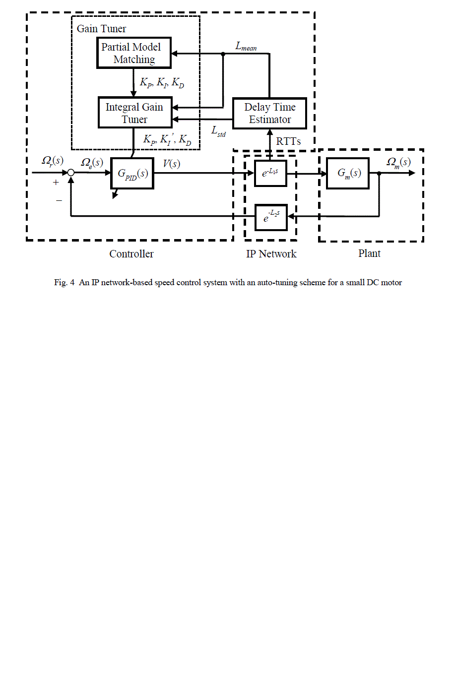
| The author proposes an auto-tuning scheme based on the partial model matching considering varying time delays for
the system shown in Fig. 1. The scheme is shown in Fig. 4, which is composed of tuning by a partial model matching
method based a dead time and re-tuning done on the characterization of the jitter by the relationship described in
previous subsection. Specifically, first, delay time estimator derives 1000 RTTs, and Lmean and Lstd from Lmean and Lmin
are computed. Second, the partial model matching of the gain tuner outputs the PID parameters KP, KI, and KD from
Lmean. Third, the integral gain tuner modifies KI in accordance with varying time delays, i.e., outputs KI’ = KI f(Lstd),
based on the relationship described in the previous subsection, from Lstd, where the formula modifying KI is empirically
adjusted. Finally, the controller GPID(s) is updated by KP, KI’, and KD. |
EXPERIMENT |
| For confirming the effectiveness of the proposed scheme, in the system shown in Fig. 4, the speed control experiments
are done under network conditions set by netem. Now the netem settings in the both direction between the controller and
the plant are as follows: |
| 1) delay, jitter and distribution are 83ms, 23ms and normal one, |
| 2) delay, jitter and distribution are 112ms, 37ms and exponential one. |
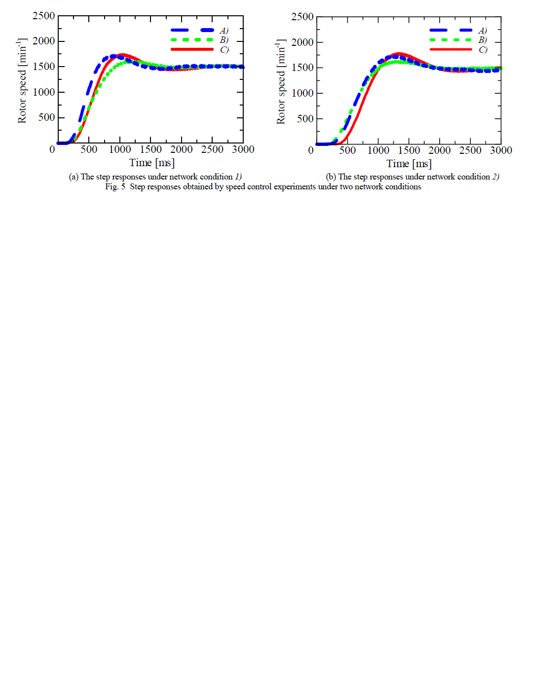
| Let r(s) = 1500min-1. Under the above network conditions, following experiments are done. First, each PID controller
is tuned by |
| A) the proposed scheme, whose output parameters are KP, KI’, and KD, |
| B) the only partial model matching method, whose output parameters are KP, KI, and KD, |
| C) for comparing C) with A) and B) and showing that A) is more effective than B), the only partial model matching
method in the system with a dead time L = Lmean. |
| The control system in the case C) is a conventional one with a dead time as shown in Fig. 2, not IP network-based one
as in Fig. 4. The response obtained in the experiment of this system is regard as one in the case without jitter, whereas
A) and B) with jitter. Hence, by comparing C) with A) and B), it can be examined whether the proposed scheme is
effective against the jitter. |
| Next, after the tuning, speed control experiments are carried out. As a result, the obtained step responses are shown
in Fig. 5, and the parameters in Table II, where is a standard deviation of the measured RTTs. In the case C), L is set
to the time close to Lmean in A) and B) for comparing them as shown in the table. The results show that, in the both cases
of 1) and 2), the responses of A) can obtain the similar ones of C) in the overshoot and the rise time. Meanwhile, the
ones of B) are obviously affected by the jitter in the overshoot. Therefore, it is found that A) can work well according to
varying time delays, especially the jitter. |
CONCLUSION |
| An auto-tuning scheme of PID controller has been proposed considering time-varying network conditions based on a partial model matching method. For confirming the effectiveness of the proposed scheme, speed control experiments have been done in an IP network-based control system of an actual small DC motor. The experimental result has been that the step response obtained using the scheme has been similar to one done after tuning the system with the constant delay time and has been improved against the jitter. Therefore it has been found that the scheme has worked well against time delays and its jitter. As a result, it has been confirmed that the scheme has been effective. |
ACKNOWLEDGMENT |
| The author would like to thank K. Shiroyama for the experimental assistant. |
Tables at a glance |
 |
| Table 1 |
|
Figures at a glance |
 |
 |
 |
 |
 |
| Figure 1 |
Figure 2 |
Figure 3 |
Figure 4 |
Figure 5 |
|
References |
- Tipsuwan, Y. and Chow, M.-Y. (2004), âÃâ¬ÃËGain Scheduler Middleware: A Methodology to Enable Existing Controllers for Networked Control and Teleoperation-Part I: Networked ControlâÃâ¬Ãâ¢, IEEE Transactions on Industrial Electronics, Vol. 51, No.6, pp. 1218-1227.
- Matsuo, K., Miura, T. and Taniguchi, T. (2007), âÃâ¬ÃËA Speed Control Method of Small DC Motor through IP Network Considering Packet LossâÃâ¬Ãâ¢, IEEJ Transactions on Electrical and Electronic Engineering, Vol. 2, No.6, pp. 657-659.
- Kitamori, T. (1979), âÃâ¬ÃËA Method of Control System Design Based upon Partial Knowledge about Controlled ProcessesâÃâ¬Ãâ¢, Transactions of the Society of Instrument and Control Engineers, Vol. 15, No. 4, pp. 549-555. (in Japanese)
- Abe, N. and Kojima, A. (2007), âÃâ¬ÃËControl in Time-delay and Distributed Parameter SystemâÃâ¬Ãâ¢, pp. 28-33, Corona Publishing. (in Japanese)
- netem, http://www.linuxfoundation.org/collaborate/workgroups/networking/netem/
- Zhao, Y.-B., Liu, G.-P. and Rees D. (2010), âÃâ¬ÃËActively Compensating for Data Packet Disorder in Networked Control SystemsâÃâ¬Ãâ¢, IEEE Transactions on Circuits and Systems II - Express Briefs, Vol.57, No.11, pp.913-917.
|