This paper presents an efficient stabilized AC Drive-Switched Capacitor Filter Compensation Scheme (SFC) for an electric vehicle (EV) using a squirrel-cage induction motor. The dynamic modelling and coordinated control strategy for the integrated-DC side switched filter-compensation scheme (SFC) with energy-recovery is fully validated for a hybrid power supply using a Lithium-Ion battery and fuel cell (FC) on the DC side with a 6-pulse VSI-inverter fed Induction motor drive. The integrated DC/AC Induction motor drive is stabilized using a hybrid SFC that ensures a fully stabilized DC Bus voltage with reduced inrush current conditions under DC side supply source and load excursions. The Lithium-Ion battery and fuel cell sources are utilized efficiently using a novel multi regulator, error driven and multi loop control strategy. The hybrid switched filter compensator is equipped with a tri-loop weighted modified PID (WMPID) controller to ensure full DC Bus stabilization and minimal inrush current conditions as well as energy recovery under deceleration and load excursions. The paper presents the validation of the DC side filtercompensation scheme and coordinated control strategy for the AC voltage source inverter using decoupled torque and flux loops of the three-phase squirrel-cage induction motor. The AC Induction motor is controlled by the first controller for different operating conditions using the direct torque control (DTC) technique, while the second controller is used to stabilize the DC common Bus and ensure energy recovery with minimal inrush current conditions. The unifiedDCAC Drive system ismodelled using MATLAB/Simulink/ Sim-power software environment.
Keywords |
| EV-AC Drive, Hybrid Fuel Cell and Lithium-Ion Battery,Switched Filter Compensator (SFC). |
INTRODUCTION |
| Electric vehicles (EVs) are emerging as a viable economical alternative to ICE fuel based transportation systems as an
elegant step to reduce pollution and Green House Gases (HGH) and reduce smog and air quality, hence reduce
environmental problems created by internal combustion engines. Besides energy-utilization efficiency and reduction in
vehicle emissions, EV can be charged by renewable energy sources such as photovoltaic solar and wind schemes.
Among current limitations of EVs is low energy density and required long charging time for the present batteries [1].
Therefore, optimal energy utilization, energy recovery and efficient electrical energy/power management is very
important in EV-DC and AC drive designs; in addition optimal design of the AC motor for weight, volume and
operating maximum efficiency at full rated condition is needed by proper selection of the unified DC-AC drive
components as well as optimal control strategies. Desired features of the propulsion system (AC motor) for an EV are
high ratios of resultant driving torque/inertia and power/volume and weight, starting and maximum torque capabilities
and accelerating torque levels are also crucial (300-400%), high speed, low level of audible noise, low maintenance,
small size, low weight, reasonable cost, high efficiency over low and high speed ranges, energy recovery on braking,
and non-sensitivity to acceleration forces. Squirrel-cage induction motors have most of the above- mentioned features
[2]. Recently, the increasing limitations imposed on the exhaust emissions from internal combustion CNG/gasoline and
diesel powered engines and the traffic restrictions in the urban areas have given a strong impulse toward the
development of electrical propulsion systems for automotive applications. The hybrid electric vehiclecomprises the
motor drive comprising of AC drive motor, a 6-pulse-VSI-power converter, speed controller, DC Bus stabilizing
filter/switched capacitor and dynamic controller to ensure energy recovery and efficient energy utilization. |
| Different types of AC motors have been proposed for use in EVs; separately excited synchronous motors, different
reluctance motors, different permanent magnet motors and Induction motors. For this drive system a squirrel-cage
induction motor is chosen due to mature technology, high reliability, high efficiency even in the high-speed range and low production cost [3]. Many control techniques have been applied on squirrel-cage Induction motors [4], [5]. The two
well-known AC Induction motor control methods are based on decoupled field-oriented control (FOC) and direct
torque control (DTC). Hybrid FOC-DTC method utilizes the advantages of the both FOC and DTC methods and at the
same time eliminates the extra required hardware and control estimation cost and complexities. So it appears to be very
suitable for EV applications. As DTC, the required measurements for this control technique are only the input currents.
Flux, torque, and speed are estimated. A loss- minimization strategy is associated with the hybrid method to maximize
the drive efficiency. Moreover, a speed estimation process and a robust flux weakening strategy are proposed and
applied to the basic drive system to make it more proper for EV applications [6-7]. |
| Induction motor has many advantages compared to DC motor, synchronous motor and switched reluctance motor in
many aspects, such as controllability, reliability, technological, maturity and cost as indicated by recent comparative
study for hybrid electric vehicles (HEV) [3], [4], [8]. Therefore, induction motor is one of the right electric motor
candidates for automotive applications. |
| Induction motors have found the primal use in all industrial applications due to their simple construction, ruggedness,
low cost, reliability, and no need for maintenance. Fast torque response and high efficiency variable speed drives are
very attractive for some special application fields that fed by limited power supply, such as electric vehicle, aerospacecraft
and so on. High dynamic performance of induction motor drives is indispensable in many applications of todays
automatically controlled machines. Induction motor control has attracted much attention recently in the power
electronics field. Field-oriented control has been developed, enabling an ac motor to attain dynamic responses as rapid
as for dc motor. The principle of field-oriented vector control is based on Fleming’s law, which describes the
interaction force between fluxes and currents. Many papershave reported the problems associated with compensating
various parameters. The current-controlled inverters typically used in the field-oriented drive system develop output
waveforms, which do not compare favourably with those of the voltage- controlled inverter. The current controlled
inverter often causes increased motor harmonic losses and acoustic noise during steady-state operation [9], [10], [11].
DTC is a suitable technology for high-performance electric drive systems. Simple algorithms, fast dynamic response
and strong robustness to parameter variation and load disturbance characterize it. Therefore, the method combined
DTC with a loss minimization approach will not only guarantee fast torque dynamic response of EV, but also maximize
operating efficiency of that [12], [13], [14]. Many control techniques have been applied on squirrel-cage induction
motors [15], [16], [17], [18], [19], [9]. Among these techniques, DTC [17], [18], [9], [20] appears to be very convenient
for EV applications. The required measurements for this control technique are only the input currents. Flux, torque, and
speed are estimated. The input of the motor controller is the reference speed, which is directly applied by the pedal of
the vehicle [7]. |
| The main objective of this paper is to design an efficient-well stabilized EV-AC drive scheme for AC induction motor
used for EV using a novel switched filter-compensation scheme and dynamic control strategies for a hybrid fuel cell
Lithium-Ion battery source. The fuel cell can be used as an additional back-energy source for hybrid EV. The selfregulating
controller is proposed based on weighted modified proportional integral derivate (WMPID) algorithm.
Theswitched filter compensator is controlled by tri-loop error-driven regulators to operate at tracking any reference
speed trajectory under varying parameter and load conditions. The control system comprises four different regulators to
track speed reference trajectory with minimum over/under current, inrush, ripple conditions. Time descaled and
decoupled multi loop control scheme has been validated for effective dynamical speed reference trajectory tracking,
efficient power utilization, limited inrush current conditions and reduced DC side transients and voltage excursions. |
SAMPLE STUDY SYSTEM |
| Figure (1) shows the proposed EV-AC induction motor drive scheme with the Lithium-Ion battery and FC. The
proposed drive system consists of five parts. There are DC voltage supplies like a Lithium-Ion battery, FC, switched
filter compensator (SFC), a controlled four IM motors for wheels, a freewheel diode, and DC load. The DC/AC
compensator scheme is used to ensure stable, efficient, minimal inrush operation of the hybrid renewable energy
scheme. The WMPID regulator and coordinated controller are used for the following purposes: |
| 1) The IM motor drive with the speed reference tracking regulator that ensure speed reference tracking with
minimum inrush conditions and ensure reduced voltage transients and improved energy utilization. |
| 2) Hybrid switched filter compensator (SFC) regulator is connected to pulse width modulated (PWM) switching
scheme to regulate the DC Bus voltage and minimize inrush current transients and load excursions. The SFC
device acts as a matching DC/DC interface device between the DC load dynamic characteristics. |
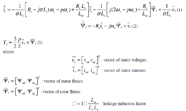
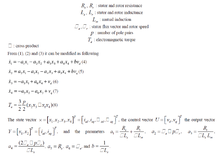
| A. Induction Motor-Model |
| The mathematic model of an induction motor in the stator-flux fixed frame, in which stator current vector and stator
flux vector act as state variables can be described by: |
 |
 |
| B. Fuel Cell Energy System Model |
| Fuel cells are electrochemical devices that convert the chemical energy of a gaseous fuel directly into electricity and are
widely regarded as a potential alternative stationary and mobile power source. FC stack systems are under intensive
development by several manufacturers, with the Polymer Electrolyte Membrane (PEM) FCs currently considered by
many to be in a relatively more developed stage for ground vehicle applications. Fuel cell stacks were connected in
series/parallel combination to achieve the rating desired. A fuel cell consists of an electrolyte sandwiched between two
electrodes. The electrolyte has a special property that allows positive ions (protons) to pass through while blocking
electrons. Hydrogen gas passes over one electrode, called an anode, and with the help of a catalyst, separates into
electrons and hydrogen protons. |
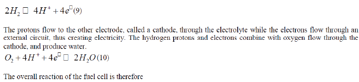 |
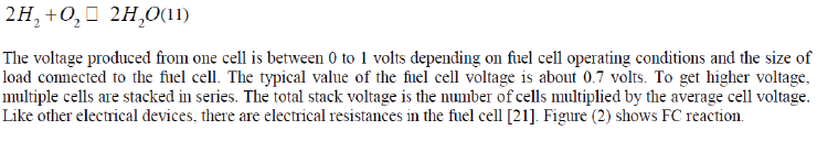 |
| C. Lithium-Ion Battery Energy System Model |
| The construction of lithium-ion battery includes a negative electrode, a positive electrode, separatorbetween the
electrodes, and electrolyte for submerging the electrodes. The negative electrodes is made of active materials including
at least one lowly graphitizes carbon material and least one highly graphitized carbon material. The positive electrode
made of active materials including lithium ion, transition metal ion and polyanion [3]. The lithium-ion battery is chosen
to be the best because it is one of the best energy density, no memory effect, long life cycle and slow loss of charge. |
CONTROL STRATEGIES |
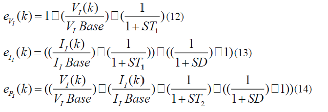
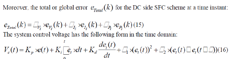
| A. Weighted Modified Proportional Integral Derivative |
| The proposed tri-loop error driven Weighted Modified Proportional Integral Derivative (WMPID) controller and shown
in Figure (3), is a novel advanced regulator concept that operates as an adaptive dynamic type multi-purpose controller
capable of handling sudden parametric changes and load and /or source excursions. By using the tri-loop error driven
WMPID controller, it is expected to have a smoother, less dynamic over-shoot, fast and more robust speed controller
when compared to those of classical control schemes. The dynamic supplementary control loops utilizes the (per-unit)
three dimensional-error vector ( eVI
,eII
,epI
) governed by the following equations: |
 |
 |
| B. Speed Control of the Induction Motor |
| PI regulator for direct torque control is considered as one of robust control for induction motor, its practical
implementation is easy in comparison with other techniques. Figure (4) represents the speed response in the case of a
variation, and inversion of speed applied to the using a classic PI regulator. The speed controller is based on the PI
regulator. Theoutput of this regulator is a torque set point applied to the DTC controller. The Direct Torque and Flux
Control (DTC) controller contains five main blocks as shown in the Figure (4). The Torque & Flux calculator is used to
estimate the motor flux αβ components and the electromagnetic torque. This calculator is based on motor equation
synthesis. The αβ vector block is used to find the sector of the αβ plane in which the flux vector lies. The Flux &
Torque Hysteresis blocks contain a two-level hysteresis comparator for flux control and a three-level hysteresis
comparator for the torque control. The Switching table block contains two lookup tables that select a specific voltage
vector in accordance with the output of the Flux & Torque Hysteresis comparators [13]. |
DIGITAL SIMULATION RESULTS |
| The Lithium-Ion and FC driven three-phase squirrel-cage induction motor is used as a propulsion system of EV
performance is compared for two test cases, namely open circuit fault and short circuit fault at common DC Bus. The
weighted modified PID has been applied to the voltage and current- tracking control of the Lithium-Ion and FC driven
scheme for performance comparison. MATLAB/Simulink software was used to design, test and validate the
effectiveness of the scheme without and with the SFC device. The digital dynamic simulation model using
MATLAB/Simulink software environment allows for low-cost assessment and prototyping, system parameters
selection and optimization of control settings. The use of weighted modified PID algorithm is used for gain adjusting to
minimize controller absolute value of total error. This is required before full-scale prototyping, which is both expensive
and time-consuming. The effectiveness of dynamic simulators brings on detailed sub-models selections and tested submodels
MATLAB library of power system components already tested and validated. The control system comprises the
three dynamic multi-loop error-driven regulators and is coordinated to minimize the selected objective functions.
Figure (5) shows the performance of the drive in a wide speed range. At time t = 0 s, the speed set point is 400 rpm. As
shown in the figure, the speed precisely follows the acceleration ramp. At t = 0.5 s, the nominal load torque is applied
to the motor. At t = 0.5 s, the speed set point is changed to 0 rpm. The speed decreases to 0 rpm. Figure (6) shows the
performance of the drive in a wide speed range. At time t = 0 s, the speed set point is 500 rpm. As shown in the
following figure, the speed precisely follows the acceleration ramp. At t = 0.5 s, the nominal load torque is applied to
the motor. At t = 1 s, the speed set point is changed to 0 rpm. The speed decreases to 0 rpm. At t = 1.5 s., the
mechanical load passes from 792 N.m to −792 N.m. Figures (7, 8) show the stator current and DC Bus voltage response
during different operation modes. Digital simulation for the EV-IM drive scheme shows the voltage and the current for
the system without SFC, with SFC with Freewheel diode. Figures (9, 10, 11, 12, 13) show the system dynamic voltage,
current and response at all Buses. In the same time, Figures (14, 15, 16, 17, 18, 19, 20, 21, 22, 23) show the system
dynamic voltage, current and response at all Buses under open circuit and short circuit fault condition at VD Bus
respectively. Figure (24) shows the performance of the drive in a wide speed range under short circuit fault at AC Bus.
Figure (25) shows the stator current and DC Bus voltage response under short circuit fault at AC Bus. |
CONCLUSIONS AND EXTENSIONS |
| The paper validated the new efficient switched filter compensation scheme and the error driven multi-loop control
strategy to ensure minimal inrush current conditions, energy recovery via the free-wheeling diode and common DC Bus
stabilization for the hybrid DC source comprising the FC and Lithium-Ion battery feeding the VSI 6-Pulse Inverter
drive for the AC three-phase squirrel-cage induction motor used as the EV-propulsion system. The scheme utilizes a
simple but effect series-parallel switched capacitor-filter to ensure dynamic terminal voltage stabilization, effective
energy utilization under load switching and faults. The dynamic modelling and coordinated control strategy for the
integrated EV drive with free-wheeling diode scheme using hybrid fuel cell and Lithium-Ion battery. The integrated
DC/AC drive scheme is stabilized using low cost pulse width modulated/switched filter compensation (SFC). The
objective of the multi loop regulator is to ensure a fully stabilized DC Bus voltage with reduced inrush current
conditions and energy recovery under source and load excursions. |
| The paper also presented the validation of the multi loop modified PID controller with additional error-squared
accelerated response and error-rate stabilization for the Lithium-ion battery, fuel cell scheme for EV powered fourwheel
AC drive using three-phase squirrel-cage induction motors. The AC induction motor is validated for different
operating conditions using the decoupled-direct torque control (DTC) technique.
The research is now extended to other AC drive systems including permanent magnet Induction motor, PMSynchronous
and Switched Reluctance motors with different SFC filter topologies and modified control strategies
using dynamic PSO/Harmony Search/Bacteria foraging and adaptive soft computing evolutionary computing dynamic
gain controllers. |
Figures at a glance |
 |
 |
 |
 |
 |
| Figure 1 |
Figure 2 |
Figure 3 |
Figure 4 |
Figure 5 |
 |
 |
 |
 |
 |
| Figure 6 |
Figure 7 |
Figure 8 |
Figure 9 |
Figure 10 |
 |
 |
 |
 |
 |
| Figure 11 |
Figure 12 |
Figure 13 |
Figure 14 |
Figure 15 |
 |
 |
 |
 |
 |
| Figure 16 |
Figure 17 |
Figure 18 |
Figure 19 |
Figure 20 |
 |
 |
 |
 |
 |
| Figure 21 |
Figure 22 |
Figure 23 |
Figure 24 |
Figure 25 |
|
References |
- D. A. J. Rand and R. Woods, “Batteries for electric vehicles,” 1981.
- F. Burke, “Batteries and ultracapacitors for electric, hybrid, and fuel cell vehicles, Proceedings of the IEEE, vol. 95, no. 4, pp. 806-820, 2007.
- M. Zeraoulia, M. E. H. Benbouzid, and D. Diallo, “Electric motor drive selection issues for HEV propulsion systems: A comparative study,” IEEE Transactions on Vehicular Technology, vol. 55, no. 6, pp. 1756-1764, 2006.
- C. Chan, “The state of the art of electric and hybrid vehicles,” Proceedings of the IEEE, vol. 90, no. 2, pp. 247-275, 2002.
- D. O. Neacsu and K. Rajashekara, “Comparative analysis of torque-controlled im drives with applications in electric and hybrid vehicles,” IEEE Transactions on Power Electronics, vol. 16, no. 2, pp. 240-247, 2001.
- M. Farasat and E. Karaman, “Speed sensorless electric vehicle propulsion system using hybrid foc-dtc induction motor drive,” in International Conference on Electrical Machines and Systems (ICEMS). IEEE, pp. 1-5, 2011.
- Faiz, M. B. B. Sharifian, A. Keyhani, and A. B. Proca, “Sensorless direct torque control of induction motors used in electric vehicle,” IEEE Transactions on Energy Conversion, vol. 18, no. 1, pp. 1-10, 2003.
- O. Ellabban, J. Van Mierlo, and P. Lataire, “Direct torque controlled space vector modulated induction motor fed by a z-source inverter for electric vehicles,” in Power Engineering, Energy and Electrical Drives (POWERENG), International Conference on. IEEE, pp.1-7, 2011.
- T. G. Habetler, F. Profumo, M. Pastorelli, and L. M. Tolbert, “Direct torque control of induction machines using space vector modulation,” IEEE Transactions on Industry Applications, vol. 28, no. 5, pp. 1045-1053, 1992.
- Takahashi and T. Noguchi, “A new quick-response and high-efficiency control strategy of an induction motor,” IEEE Transactions on Industry Applications, no. 5, pp. 820-827, 1986.
- M. Aware, S. Tarnekar, and J. G. Chaudhari, “Improved direct torque control induction motor drive,” in TENCON 2006. IEEE Region 10 Conference. IEEE, pp. 1-4, 2006.
- R. H. Daugherty and C. H. Wennerstrom, “Need for industry standards for AC induction motors intended for use with adjustable-frequency controllers,” IEEE Transactions on Industry Applications, vol. 27, no. 6, pp. 1175-1185, 1991.
- B. K. Bose, Modern power electronics and AC drives. Prentice hall USA, vol. 712, 2002.
- Z. Xinghua, Z. Houbei, and S. Zhenxing, “Efficiency optimization of direct torque controlled induction motor drives for electric vehicles,” in Electrical Machines and Systems (ICEMS), International Conference on. IEEE, pp. 1-5, 2011.
- U. Choietet al., “A high efficiency drive system for electric vehicle,” IEVS-13, pp. 537-543, 1996.
- Matsus and S. Katsuta, “Fast rotor flux control of vector controlled induction motor operating at maximum efficiency for electric vehicles,” EVS-13, p272-278, 1996.
- Faiz, S. Hossieni, M. Ghaneei, A. Keyhani, and A. Proca, “Direct torque control of induction motors for electric propulsion systems,” Electric power systems research, vol. 51, no. 2, pp. 95-101, 1999.
- U. Baader, M. Depenbrock, and G. Gierse, “Direct self control (dsc) of inverter-fed induction machine: A basis for speed control withoutspeed measurement,” IEEE Transactions on Industry Applications, vol. 28, no. 3, pp. 581-588, 1992.
- O. Kukrer, “Discrete-time current control of voltage-fed three-phase pwm inverters,” IEEE Transactions on Power Electronics, vol. 11, no. 2, pp. 260-269, 1996.
- P. Vas, Sensorless vector and direct torque control. Oxford university press Oxford, UK, 1998.
- James and D. Andrew, “Fuel cell systems explained,” John Wiley & Sons, Ltd., Chichester, 2003.
|