International Journal of Advanced Research in Electrical, Electronics and Instrumentation Engineering
ISSN ONLINE(2278-8875) PRINT (2320-3765)
ISSN ONLINE(2278-8875) PRINT (2320-3765)
Deepika1 and Pankaj Mehara2
|
| Related article at Pubmed, Scholar Google |
Visit for more related articles at International Journal of Advanced Research in Electrical, Electronics and Instrumentation Engineering
An efficient analytical technique using Secant method is used to describe the generated frequency and saturated magnetizing reactance of self-excited induction generator for a given capacitance, speed, and load. The nodal technique is used on the single phase equivalent circuit of SEIG. The nodal analysis provides two non- linear equations. One equation contain only generated frequency term solve by Secant method using initial values calculation by real power balance equivalent circuit. This proposed technique is simple and used for any kind of balanced load.
Keywords |
||||||||||||||||||
| Self-excited induction generator, Secant method, Non-linear equations. | ||||||||||||||||||
INTRODUCTION |
||||||||||||||||||
| The increasing concern to the environment and fast depleting conventional resources have cause the researchers towards rationalizing the use of conventional energy resources and motivating the non-conventional energy resources to meet the energy demand. A number of renewable energy sources like small hydro, wind, solar, industrial waste, geothermal, etc. are explored. Since small hydro and wind energy sources are available in plenty, their utilization is felt quite promising to accomplish the future energy requirements. Harnessing mini-hydro and wind energy for electric power generation is an area of research interest and at present, the emphasis is being given to the cost-effective utilization of these energy resources for quality and reliable power supply. Induction generators are often used in wind turbines and some micro hydro installations due to their capability to produce useful power at varying speeds [1]. | ||||||||||||||||||
| If an appropriate three phase capacitor bank is connected across the induction machine driven by external source, the EMF is induced in the machine winding due to excitation provided by the capacitor bank. This phenomenon is known as capacitor excitation which is important thing to operate the induction machine as a generator. An induced voltage and current will be continues rise and finally reached at steady state due to magnetic saturation in the machine. | ||||||||||||||||||
| The induction machine having the following advantages over synchronous machine as a source of isolated power supply. Operated as a varying speed, reduced unit cost, brushless rotor construction (squirrel cage rotor), no separate DC source i s required for excitation and ease of maintenance is the following advantages. | ||||||||||||||||||
| The steady state analysis is very important for design as well as operational point of view. If the machine is connected to infinite bus bar, the terminal voltage and frequency are known, the prediction of the performance of the machine is straightforward. But in case of self-excited induction generator used as a stand-alone purpose , both the terminal voltage and generated frequency are unknown, to determine the performance of machine the unknowns have to computed for given speed, capacitance and load [2]- [9]. The calculation is complicated due to magnetic saturation, so a suitable parameter is used to calculate the performance in the saturated condition. The Secant method is used in this paper to identify the steady state performance using the single phase equivalent circuit of the self-excited induction generator. In the Secant method the initial values of generated frequency is determined by using real power balance equivalent circuit. The result is discussed and presented graphically to guidelines for designers. | ||||||||||||||||||
THEORY |
||||||||||||||||||
| For steady state analysis the following assumption are taken | ||||||||||||||||||
| • Only the magnetizing reactance is assumed to be changes by magnetic saturation, and all the other parameters remains constant. | ||||||||||||||||||
| • Stator and rotor leakage reactance are assume equal. | ||||||||||||||||||
| • Core losses in the machine are neglected. | ||||||||||||||||||
| • MMF space harmonics and time harmonics in the induced voltage and current waveforms are ignored. These all assumptions are valid for well design machine. | ||||||||||||||||||
| The steady state equivalent circuit of capacitor self-excited induction generator with resistive load connected to its terminal as shown in fig. 1 where : | ||||||||||||||||||
 |
||||||||||||||||||
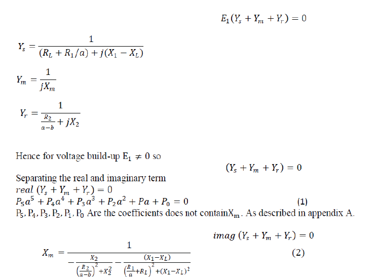
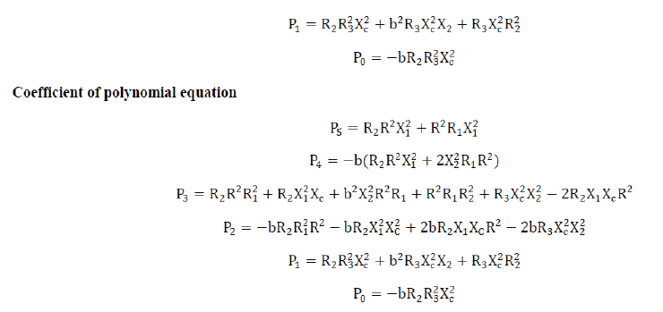
| The equivalent per phase circuit of SEIG as shown by fig.1 which is only valid for generated frequency. Here use nodal analysis technique to determine generated frequency and magnetizing reactance at node M.This analysis considers the admittances connected across the nodes which define the air gap. By equating the sum of real parts to zero (which is equivalent to active power balance), a polynomial in „a‟ is obtained. „Xm‟ can be determined upon equating the sum of imaginary parts to zero, using the value of „a‟ obtained after solving the polynomial by any method among various methods as iterative method, secant method etc. | ||||||||||||||||||
 |
||||||||||||||||||
| Since the equation (1) contain frequency term and this polynomial equation can be solved by secant method using initial values calculation then compute the value of frequency in equation (2) to calculate the value of . | ||||||||||||||||||
INITIAL VALUES CALCULATION TECHNIQUE |
||||||||||||||||||
| The Secant method requires two initial values for solving a polynomial equation. Here the two initial values can be calculated by real power balance equivalent circuit. | ||||||||||||||||||
| The equation (1) can be rewritten as a function of a | ||||||||||||||||||
| f a = 0 | ||||||||||||||||||
| If a0 and a1 are two initial values for a. Then the next value for a will be: | ||||||||||||||||||
| ai+1 = ai − f(ai)(ai − a0)/(f ai − f(a0)) | ||||||||||||||||||
| i = 1, 2, 3 . . . | ||||||||||||||||||
| The iterations stop with an accuracy of 0.000001. | ||||||||||||||||||
| The desired value of a lies between upper initial value (a0) and lower initial value (ai) | ||||||||||||||||||
The upper initial value (a0) |
||||||||||||||||||
| The real power balance equation according to the fig. 3 | ||||||||||||||||||
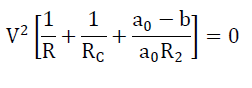 (3) (3) |
||||||||||||||||||
| Since V2 cannot be zero, solve the equation (3) for a0 | ||||||||||||||||||
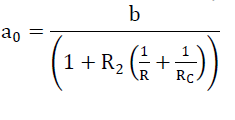 (4) (4) |
||||||||||||||||||
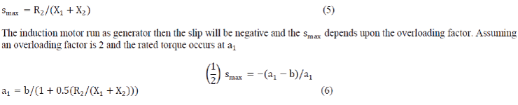
| Lower initial value (a1) | ||||||||||||||||||
| Lower initial value can be found out by assuming a very close value at which maximum torque occur. | ||||||||||||||||||
 |
||||||||||||||||||
SYNCHRONOUS SPEED TEST |
||||||||||||||||||
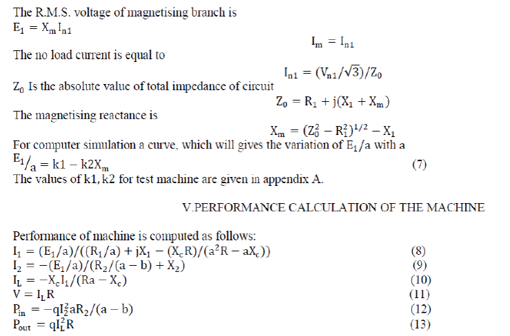
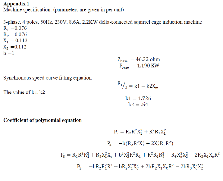
| After solving the value of the next step is to calculate the airgap voltage 1 and the terminal voltage . The synchronous speed provide the information about the variation of with respect to 1 which relate to the air gap flux. These information require to be obtained experimentally by driving the induction machine at synchronous speed corresponding to line frequency, i.e. a=1 and measuring the magnetizing reactance with increase the line voltage at line frequency according the fig.4. When the induction machine rotated at synchronous speed the slip will become zero and rotor resistance become very high and behave as an open circuit on rotor side. A curve fitted of 1 against by the experimental result. | ||||||||||||||||||
 |
||||||||||||||||||
RESULT AND DISCUSSION |
||||||||||||||||||
| Here the effective secant method is used to find generated frequency and magnetizing reactance and a terminal voltage is computed at resistive loads and at constant speed and with fixed capacitor value. Further check the performance of machine at different values of capacitance. And provide a table to require the value of capacitance which remains constant the terminal voltage at different load condition. | ||||||||||||||||||
CONCLUSION |
||||||||||||||||||
| This paper introduced the efficient approach to calculate initial values of generated frequency with the help of real power balanced circuit. This technique is simple in nature and very effective to analyse the SEIG. This technique is suitable for any kind of balance load. The paper describes the value of capacitance required to maintain the specific terminal voltage across the load which is varying in nature. | ||||||||||||||||||
Tables at a glance |
||||||||||||||||||
|
||||||||||||||||||
Figures at a glance |
||||||||||||||||||
|
||||||||||||||||||
References |
||||||||||||||||||
|
||||||||||||||||||
 |
||||||||||||||||||
 |


