International Journal of Advanced Research in Electrical, Electronics and Instrumentation Engineering
ISSN ONLINE(2278-8875) PRINT (2320-3765)
ISSN ONLINE(2278-8875) PRINT (2320-3765)
B. Sai Bhargavi1 and P. Praveen Kumar2
|
| Related article at Pubmed, Scholar Google |
Visit for more related articles at International Journal of Advanced Research in Electrical, Electronics and Instrumentation Engineering
This paper presents “an advanced fully fault tolerant communication by FSD-ECC with low power consumption and more security” To prevent soft errors from causing data corruption, memories are typically protected with error correction codes. An advanced error correction codes are used when an additional protection is needed. a fully fault-tolerant memory architecture that is capable of tolerating hardware or software errors not only in the memory bits but also in the supporting logic including the ECC encoder and corrector with low power consumption and more security. This project uses a Euclidean Geometry codes, SEA (Scalable Encryprion Algorithm). Hence proved that these codes are part of a new subset of ECCs that have FSD(fault secure detector - error correcting code).This is useful as majority logic decoding can be implemented serially with simple hardware but requires a large decoding time. For memory applications, this increases the memory access time. The method detects whether a word has errors in the first iterations of majority logic decoding, and when there are no errors the decoding ends without completing the rest of the iterations. Since most words in a memory will be error-free, the average decoding time is greatly reduced. In this brief, we study the application of a similar technique to a class of Euclidean geometry low density parity check (EGLDPC) codes that are one step majority logic decodable. The results obtained show that the method is also effective for EG-LDPC codes. Other than this LDPC codes satisfies a new, restricted definition for ECCs which guarantees that the ECC codeword has an appropriate redundancy structure such that. it can detect multiple errors occurring in both the stored codeword in memory and the surrounding circuitries. which makes the area overhead minimal and keeps the extra power consumption low. Extensive simulation results are given to accurately estimate the probability of error detection for different code sizes
INTRODUCTION |
||||||||||||
| Memory cells have been protected from soft errors for more than a decade, due to the increase in soft error rate in logic circuits, the encoder and decoder circuitry around the memory blocks have become susceptible to soft errors as well and must also be protected. A fault- tolerant nano-scale memory architecture which tolerates transient faults both in the storage unit and in the supporting logic (i.e., encoder, decoder, corrector and detector circuitries) is introduced. | ||||||||||||
| Transient faults: When a node in the system loses its effective charge due to ionized particle hit or various sources of noises, it may cause the value of a node to be flipped in the circuit. However, the error does not permanently change the circuit, and it only generates a faulty bit value at the node that can last for one or few cycles. The transient fault rate is the probability that a single node loses its correct value during one clock cycle. Feature-size scaling, faster clock cycles and lower power designs increase the transient fault rate. Feature-size scaling and voltage level reduction shrinks the amount of critical charges holding logical state on each node; this in turn makes each node more susceptible to transient faults, e.g., an ionized particle strike has higher likelihood of being fatal as the critical charge is reduced in a node, which may cause a glitch or bit-flip. Furthermore operating at higher clock frequency increases the probability that a glitch in the signal is latched and propagated as an erroneous value throughout the circuit. However, many transient faults will not be latched. Some of the latched data may not be relevant to machine operation and there will be no perceivable error in the program operation. Hence, the effective error rate of a large combinational circuit needs to be dreaded Particularly, a class of error-correcting codes (ECCs) that guarantees the existence of a simple fault-tolerant detector design is identified. This class satisfies a new, restricted definition for ECCs which guarantees that the ECC codeword has an appropriate redundancy structure such that it can detect multiple errors occurring in both the stored codeword in memory and the surrounding circuitries. This type of error-correcting codes are called as fault-secure detector capable ECCs (FSD-ECC). The parity-check Matrix of an FSD-ECC has a particular structure that the decoder circuit, generated from the parity-check Matrix, is Fault-Secure. The ECCs identified in this class is close to optimal in rate and distance, suggesting we can achieve this property without sacrificing traditional ECC metrics. The faultsecure detection unit is used to design a fault-tolerant encoder and corrector by monitoring their outputs. If a detector detects an error in either of these units, that unit must repeat the operation to generate the correct output vector. Using this retry technique, potential transient errors in the encoder are corrected and provide a fully fault-tolerant memory system. | ||||||||||||
Single Event Upsets (SEU) |
||||||||||||
| Nowadays, single event upsets (SEUs) altering digital circuits are becoming a bigger concern for memory applications.A single event upset (SEU) is a change of state caused by ions or electro-magnetic radiation striking a sensitive node in a micro-electronic device, such as in a microprocessor, semiconductor memory, or power transistors. The state change is a result of the free charge created by ionization in or close to an important node of a logic element (e.g. memory "bit"). The error in device output or operation caused as a result of the strike is called an SEU or a soft error.The SEU itself is not considered permanently damaging to the transistor's or circuits' functionality unlike the case of single event latchup (SEL), single event gate rupture (SEGR), or single event burnout (SEB). These are all examples of a general class of radiation effects in electronic devices called single event effects. Terrestrial SEU arise due to cosmic particles colliding with atoms in the atmosphere, creating cascades or showers of neutrons and protons, which in turn may interact with electronics. At deep sub-micrometre geometries, this affects semiconductor devices in the atmosphere. If the radiation event is of a very high energy, more than a single bit maybe affected, creating Multi Bit Upset (MBU). For reliable communication, errors must be detected and corrected. Error detection is the way to find out that is a data is correct or incorrect. Reed-Muller is one of the methods of multiple error detection in blocks for digital communications signals. Soft error reliability is to employ Error Detection and Correction (EDAC) techniques or Error Correction Codes (ECC) is employed. Various error detection techniques are used to avoid the soft error. One of the methods is majority logic decoder which used to detect and correct the error in simple way. The drawback of this method is increase the average latency of the decoding process because it depends on the size of the code. Another method is syndrome fault detector which increase the power consumption because it is complex module. Majority Logic Decoder/Detector (MLDD) is used for avoiding those drawbacks of existing methods. For terrestrial radiation environments where there is a low soft error rate (SER), codes like single error correction and double error detection (SEC–DED), are a good solution, due to their low encoding and decoding complexity. However, as a consequence of augmenting integration densities, there is an increase in the number of soft errors, which produces the need for higher error correction capabilities. | ||||||||||||
Error correction edit |
||||||||||||
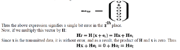
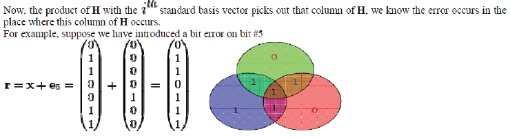
| It suppose a single bit error has occurred. Mathematically, we can write modulo 2, where ei is the unit vector, that is, a zero vector with a 1 in the ith, counting from 1. | ||||||||||||
 |
||||||||||||
 |
||||||||||||
| A bit error on bit 5 causes bad parity in the red and green circles The diagram to the right shows the bit error (shown in blue text) and the bad parity created (shown in red text) in the red and green circles. The bit error can be detected by computing the parity of the red, green, and blue circles. If a bad parity is detected then the data bit that overlaps only the bad parity circles is the bit with the error. In the above example, the red & green circles have bad parity so the bit corresponding to the intersection of red & green but not blue indicates the errored bit. Now, | ||||||||||||
 |
||||||||||||
Decoding edit |
||||||||||||
| Once the received vector has been determined to be error-free or corrected if an error occurred (assuming only zero or one bit errors are possible) then the received data needs to be decoded back into the original 4 bits. | ||||||||||||
ECC with Fault Secure Detector |
||||||||||||
| Single-error fault-tolerant decoder and encoder circuits for Reed-Solomon codes have been suggested in. In this work the encoder is protected with parity-prediction and parity checker. The decoder is protected by adding a code checker (detector) block and a hamming distance counter block to count the number of error bits at the output of the decoder. If the code checker detects a non-codeword, then the error in the decoder is detected. If the code checker detects a codeword but the hamming-distance counter indicate a non-zero error, then an error is also detected. Here we propose a multiple-error fault tolerant decoder and encoder that is general enough for any decoder and encoder implementation and for any kind of ECC that satisfies the restricted ECC definition. The restricted ECC definition which guarantees a fault-secure detector capable ECC (FSD-ECC) is as follows: Let C be an ECC with minimum distance d. C is FSDECC if it can detect any combination of overall d − 1 or fewer errors in the received codeword and in the detector circuitry. | ||||||||||||
| The following proof depends on the fact that any single error in the detector circuitry can corrupt at most one output (one syndrome bit). This can be easily satisfied for any type of circuitry by implementing the circuit in such a way that no logic element is shared among multiple output bits, therefore any single error in the circuit corrupt at most one output (one syndrome bit). | ||||||||||||
| Proof: The core of a detector circuitry is a multiplier that implements the vector-matrix multiply of the received vector and the parity-check matrix to generate the syndrome vector. Now if e errors strike the received code-vector the syndrome weight of the error pattern is at least d − e from the assumption. Furthermore, the maximum number of tolerable errors in the whole system is d − 1 and e errors already exist in the encoded vector, therefore the maximum number of errors that can strike in the detector circuitry is d − 1 − e. From the above note, this many errors can corrupt at most d − 1 − e syndrome bit, which in worst case leaves at least one non-zero syndrome bit and therefore detects the errors. Q.E.D The difference between FSD-ECC and normal ECC is the demand on syndrome weight: i.e., a normal ECC demands non-zero syndrome weight while FSD-ECC demands > d − e. | ||||||||||||
LOW DENSITY PARITY CHECK CODES |
||||||||||||
| In information theory, a low-density parity-check (LDPC) code is a linear error correcting code, a method of transmitting a message over a noisy transmission channel.[1][2] An LDPC is constructed using a sparse bipartite graph.[3] LDPC codes are capacity-approaching codes, which means that practical constructions exist that allow the noise threshold to be set very close (or even arbitrarily close on the BEC) to the theoretical maximum (the Shannon limit) for a symmetric memory less channel. The noise threshold defines an upper bound for the channel noise, up to which the probability of lost information can be made as small as desired. Using iterative belief propagation techniques, LDPC codes can be decoded in time linear to their block length. LDPC codes are finding increasing use in applications requiring reliable and highly efficient information transfer over bandwidth or return channel-constrained links in the presence of corrupting noise. Implementation of LDPC codes has lagged behind that of other codes, notably turbo codes. The fundamental patent for Turbo Codes expired on August 29, 2013.LDPC codes are also known as Gallager codes, in honor of Robert G. Gallager, who developed the LDPC concept in his doctoral dissertation at the Massachusetts Institute of Technology in 1960. | ||||||||||||
| In 2003, an LDPC code beat six turbo codes to become the error correcting code in the new DVB-S2 standard for the satellite transmission of digital television. [9] The DVB-S2 selection committee made decoder complexity estimates for the Turbo Code proposals using a much less efficient serial decoder architecture rather than a parallel decoder architecture. This forced the Turbo Code proposals to use frame sizes on the order of one half the frame size of the LDPC proposals. In 2008, LDPC beat convolutional turbo codes as the forward error correction (FEC) system for the ITU-T G.hn standard.[10]G.hn chose LDPC coded over turbo codes because of their lower decoding complexity (especially when operating at data rates close to 1.0 Gbit/s) and because the proposed turbo codes exhibited a significant error floor at the desired range of operation.[11] LDPC is also used for 10GBase-T Ethernet, which sends data at 10 gigabits per second over twisted-pair cables. As of 2009, LDPC codes are also part of the Wi-Fi 802.11 standard as an optional part of 802.11n and 802.11ac, in the High Throughput (HT) PHY specification.Some OFDM systems add an additional outer error correction that fixes the occasional errors (the "error floor") that get past the LDPC correction inner code even at low bit error rates. For example: The Reed-Solomon code with LDPC Coded Modulation (RS-LCM) uses a Reed-Solomon outer code.[13] The DVB-S2, the DVB-T2 and the DVB-C2 standards all use aBCH code outer code to mop up residual errors after LDPC decoding. | ||||||||||||
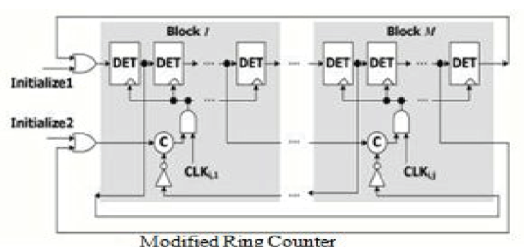
Design structure of Ring counter with clock gated by CG-element |
||||||||||||
| As the extra RS- flip flops still serve as loading of the clock signal and demand more than necessary clock power, the idea is to replace the RS-flip flop by a CG-element which greatly reduce the power consumption. Additionally, replacing D-flip flops by DET flip-flops reduce the clock rate to half and thus also reduce the power consumption on the clock signal. | ||||||||||||
Modified Ring Counter |
||||||||||||
 |
||||||||||||
| In this paper for improving the power consumption and efficient operation of clock pulse a modified ring counter is used see fig above | ||||||||||||
Clock Gated D Flip-Flop |
||||||||||||
| An assumption is made that all transitions on Q (output data) should be synchronized with an active clock edge. Data miscommunication errors might be caused due to asynchronous data sampling. The CG (clock gating control) signal is activated when there is a transition in D (input data). Flip-flop is triggered when internal clock pulse is given. The C (internal gated clock) signal maintains its value instead of generating an active edge in the gating mode. C changes after the transition on CLK in the non-gating mode. Asynchronous data transition may occur, if D changes (i.e., it enters the non-gating mode) while C is not equal to CLK and is shown as spikes at the output. synchronous Sampling in the Gated Double Edge-Triggered Flip-Flop with Transmission Gate (G_DETFF) The flip-flop is built with the Latch-Mux structure using transmission gates as in Fig 1. The two data paths are connected in parallel. The upper data path transmits data on the rising edge and the lower path transmits data on the falling edge. These two data paths alternatively monitor the input and provide the output, which means that the input is always preloaded into the flip-flop. | ||||||||||||
| Instead of generating a pulse for every transition, the clockgating part was designed to toggle C, whenever the data input is changed and also to eliminate power consumption for unnecessary transitions. During the gating periods, C preserves the last used value before being gated. When compared to other clock gating techniques, G_DETFF uses the clock signal in a more efficient way that is better suited for DETFF | ||||||||||||
SYSTEM OVERVIEW |
||||||||||||
| The memory system which can tolerate errors in any part of the system, including the storage unit, encoder and corrector circuit, using the fault-secure detector is shown below. There is a fault secure detector that can detect any combination of errors in the received code-word along with errors in the detector circuit. This fault-secure detector can verify the correctness of the encoder and corrector operation. An overview of the proposed fault secure encoder and decoder is shown in figure 3.1, and is as described below. | ||||||||||||
| Block diagram of Fault Secure Encoder and Decoder. The information bits are fed into the encoder to encode the information vector, and the fault secure detector of the encoder verifies the validity of the encoded vector. If the detector detects any error, the encoding operation must be redone to generate the correct code-word. The code-word is then stored in the memory. Later during operation, the stored codeword will be retrieved from the memory unit. Since the code-word is susceptible to transient faults while it is stored in the memory, the retrieved code-word must be fed into the detector to detect any potential error and possibly to the corrector to recover any erroneous bits. In this design the corrector circuit has parallel structure and is implemented fully pipelined similar to the detector. All the memory words are pipelined through the corrector and then detector, therefore, one corrected memory word is generated every cycle. The detector following the corrector, would raise an error-detection flag only if a transient fault occurs in the corrector or detector circuitry. Due to the relative lower transient fault rate compared to the permanent defects and the relative small corrector and detector circuitry, this happens with low frequency. Therefore, the potential throughput loss of this system is low. | ||||||||||||
Design Structure |
||||||||||||
| In this section the design structure of the encoder, corrector, and detector units of the proposed fault secure encoder and decoder is provided. Encoder: An n-bit code-word c, which encodes k-bit information vector i is generated by multiplying the k-bit information vector with k × n bit generator matrix G, i.e., c = i · G. Figure 3.2 shows the generator matrix of (15, 7) EG-LDPC code. all the rows of the matrix are cyclic shifts of the first row. This cyclic code generation does not generate a systematic code and the information bits must be decoded from the encoded vector, which is not desirable for our fault-tolerant approach due to the further complication and delay that it adds to the operation. The generator matrix of any cyclic code can be converted into systematic form (G = [I : X]) | ||||||||||||
DET (Double edge triggered flip-flops) |
||||||||||||
| Double-edge-triggered (DET) flip-flops are utilized to reduce the operating frequency by half The logic construction of a double-edge-triggered (DET) flip-flop, which can receive input signal at two levels the clock, is analyzed and a new circuit design of CMOS DET In this paper, we propose to use double-edge-triggered (DET) flip-flops instead of traditional DFFs in the ring counter to halve the operating clock frequency. Double edge-triggered flipflops are becoming a popular technique for lowpower designs since they effectively enable a halving of the clock frequency. The paper by Hossain etal showed that while a single-edge triggered flipflop can be implemented by two transparent latches in series, a double edge-triggered flipflop can be implemented by two transparent latches in parallel. | ||||||||||||
C ELEMENT |
||||||||||||
| The Muller C-element, or Muller C-gate, is a commonly used asynchronous logic component originally designed by David E. Muller. It applies logical operations on the inputs and has hysteresis. The output of the C-element reflects the inputs when the states of all inputs match. The output then remains in this state until the inputs all transition to the other state. This model can be extended to the Asymmetric C-element where some inputs only effect the operation in one of the transitions (positive or negative). The figure shows the gate-level and transistor-level implementations and symbol of the C-element. | ||||||||||||
| One-step majority-logic correction is a fast and relatively compact error-correcting technique. There is a limited class of ECCs that are one-step-majority correctable which include type-I two-dimensional EG-LDPC. In this section, we present a brief review of this correcting technique. Then we show the one step majority-logic corrector for EG-LDPC codes. | ||||||||||||
Power Reports |
||||||||||||
| The power reports of the existing and proposed systems are as shown below. The table 1 shows the power report of the existing system and the table 9.2 shows the power report of the proposed system. The power consumed by the existing system is 914mw and the power consumed by the proposed system is 229mw and the difference between the both existing and proposed power consumptions is of 39% difference. | ||||||||||||
Fault Secure Detector: |
||||||||||||
| The core of the detector operation is to generate the syndrome vector, which is basically implementing the following vector-matrix multiplication on the received encoded vector c and parity-check matrix H. C T H = S The C-element stores its previous state with two cross-coupled inverters, similar to an SRAM cell. One of the inverters is weaker than the rest of the circuit, so it can be overpowered by the pull-up and pull-down networks. | ||||||||||||
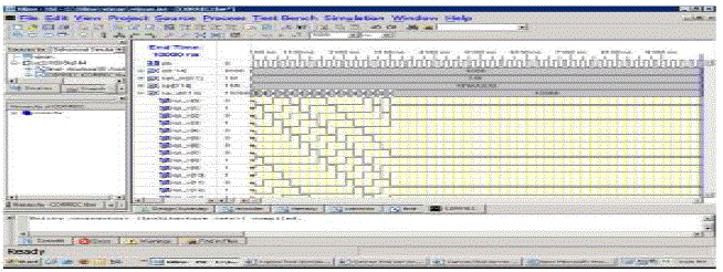
Serial one-step majority logic corrector structure Simulation Results Synthesis Reports: |
||||||||||||
 |
||||||||||||
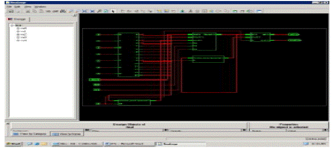
RTL Schematic: |
||||||||||||
 |
||||||||||||
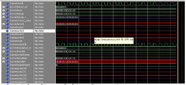
wave form of the corrector |
||||||||||||
 |
||||||||||||
| 38% power reduction is observed in proposed technique with more security | ||||||||||||
CONCLUSION |
||||||||||||
| In this report, a fully fault-tolerant memory system that is capable of tolerating errors not only in the memory but also in the supporting logic is designed. The LDPC codes are proved as part of a new subset of FSD-ECCs. Using these FSDs a fault-tolerant encoder and corrector is designed. Here for low power we have used the C elements and provided security for the fault tolerant system by using the Scalable Encryption Algorithm to encrypt and Decrypt the data. | ||||||||||||
Tables at a glance |
||||||||||||
|
||||||||||||
Figures at a glance |
||||||||||||
|
||||||||||||
References |
||||||||||||
|


