International Journal of Advanced Research in Electrical, Electronics and Instrumentation Engineering
ISSN ONLINE(2278-8875) PRINT (2320-3765)
ISSN ONLINE(2278-8875) PRINT (2320-3765)
Rojin R.K1 and Ajay Amrit Raj2
|
| Related article at Pubmed, Scholar Google |
Visit for more related articles at International Journal of Advanced Research in Electrical, Electronics and Instrumentation Engineering
Power quality issues are of great concern in transmission and distribution system nowadays due to the sensitive nature of the loads. The sensitive nature of the load increases with the advent of power electronic technology. In distribution systems, current harmonics, voltage sag/swell are more prominent. Power quality problems cannot be eliminated by using conventional filters. Therefore power electronic based active power filters (APF) are most commonly used nowadays. Unified Power Quality Conditioner (UPQC) is a custom power device, used to enhance power quality in distribution system. UPQC is an integration of shunt and series active power filter. In this paper fuzzy logic controller (FLC) based UPQC for a 3 phase 4 wire distribution system is proposed. The proposed system has the capability to mitigate power quality problems in a cost effective manner with reduced dc link voltage rating. The proposed system eliminates the limitations of PI controller. In this paper hysteresis controller is used to control the voltage source inverter (VSI) switches of UPQC. The performance of the proposed system is verified using MATLAB/Simulink.
Keywords |
||||||||||||||||||||
| Custom power device, distribution static compensator (D-STATCOM), dynamic voltage restorer (DVR), voltage source inverter (VSI), PI controller, Fuzzy logic controller (FLC) | ||||||||||||||||||||
INTRODUCTION |
||||||||||||||||||||
| Poor power quality in power system could be due to different factors, such as poor power factor, voltage sag, voltage swell, and unaccepted level of harmonics in voltage and current waveforms [1]. These power quality problems are due to the use of sophisticated nonlinear equipment/loads at transmission and distribution level. The usage of the nonlinear equipment and loads in the power system increases with the advent of power electronic devices. These devices require high quality power to work properly, at the same time produces harmonics in the system. Some examples for nonlinear loads are adjustable speed drives (ASD), switched mode power supplies (SMPS), uninterrupted power supplies (UPS) etc. More over in distribution systems, when an unbalance occurs zero sequence currents will flow through neutral. The elimination or mitigation of disturbances propagated from the distribution system is absolutely required to improve the operational reliability of these loads. | ||||||||||||||||||||
| In this work power quality enhancement using UPQC in distribution system is considered. Voltage sag, voltage swell, harmonics, inter harmonics etc. are some of the power quality problems caused by these devices in distribution system [2]. The terminology and the guidelines for power quality has been described in detail at IEEE-519 and IEC-555. According to these guidelines, the voltage sag or swell is allowed by 10%, the total harmonic distortion is allowed by 5%, and the voltage unbalance is allowed by 10% [3],[4]. To provide a balance, distortion-free, and constant magnitude power to sensitive load and, at the same time, to restrict the harmonic, unbalance, and reactive power demanded by the load and hence to make the overall power distribution system more healthy, the unified power quality conditioner (UPQC) is one of the best solutions. Custom power devices have been proposed for enhancing the quality and reliability of electrical power [5]. | ||||||||||||||||||||
| In this paper UPQC using fuzzy logic controller for a 3 phase 4 wire systems is considered. In this topology the neutral terminal is also considered. Here linear and nonlinear load is considered for analysis, since loads in a distribution system consists of both linear and nonlinear loads. A combination of hysteresis controller and fuzzy logic controller is used to control the gating pulse of the switching devices (IGBTs) in shunt and series active filters. Fuzzy logic controller is used to maintain voltage across the dc link capacitor bank. | ||||||||||||||||||||
| The performance of UPQC mainly depends upon how quickly and accurately compensation signals are derived. Control schemes of UPQC based on PI controller has been widely reported [6], [7]. The PI control based techniques are simple in design and reasonably. However, the tuning of the PI controller is a tedious job. Further, the control of UPQC based on the conventional PI control is prone to severe dynamic interaction between active and reactive power flows [6]. In this work, the conventional PI controller has been replaced by a fuzzy logic controller. The fuzzy logic controller has been used in APFs in place of conventional PI controller for improving the dynamic performance [20]. The FC is basically nonlinear and adaptive in nature. The results obtained through FC are superior in the cases where the effects of parameter variation of controller are also taken into consideration [21]. The proposed system has manyadvantages such as fast controllability, efficient design and reduced switching losses over conventional neutral clamped UPQC systems or four-leg shunt active filter UPQC systems [8]. MATLAB/Simulink is used to verify the results of the proposed system. | ||||||||||||||||||||
RELATED WORKS |
||||||||||||||||||||
| Many studies were reported based on power quality enhancement using UPQC for distribution systems in [8], [15], [10] and [11], since power quality problems were increasing. UPQC for a 3 phase 4 wire system derived from a 3 phase 3 wire system using a delta/star transformer dealt with 3 phase loads alone is reported in [8]. The neutral terminal of the transformer is directly earthed. UPQC using 4 leg VSIs for shunt active filter is explained in [11]. Voltage balancing across dc link terminal for shunt and series active filter is one of its draw back. Also the system is bulky and losses were there in the fourth leg. UPQC using neutral clamped topology were reported in [10]. It uses a higher value dc link capacitor, which increases the size and weight of the system. A modern technique of connecting neutral terminal to ground and negative terminal of the capacitor bank is proposed in [15]. Here bulkiness is reduced. But tuning of PI controller creates many problems. In [12], a new topology is developed for a three-phase four-wire (3P4W) distribution system utilizing a zig-zag transformer along with three-phase three wire(3P3W) Unified Power Quality Conditioner (UPQC). The neutral point of the star connected transformer, used for the connection of series active power filter (APF) of 3P3W UPQC, is utilized as a fourth wire for 3P4W distribution system. | ||||||||||||||||||||
UNIFIED POWER QUALITY CONDITIONER (UPQC) |
||||||||||||||||||||
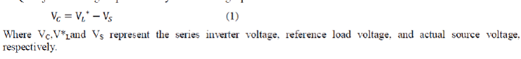
| UPQC is a power electronic device which consists of two IGBT based voltage source inverters (VSI) connected backto- back through a common dc-link capacitor. It isused to mitigate both load current and supply voltage imperfections. UPQC can simultaneously act as shunt and series active power filters; that is it can compensate for voltage and current related power quality problems simultaneously. The basic configuration of UPQC is shown in fig.1.The series part of the UPQC is known as dynamic voltage restorer (DVR). It is used to maintain balanced, distortion free nominal voltage at the load.The series active filter inserts a voltage, which is added at the point of the common coupling (PCC) such that the voltage at the load end remains unaffected by any voltage disturbance [13]. Whenever the supply voltage undergoes sag then series converter injects suitable voltage with supply. The series inverter of the UPQC injects a voltage represented by the following equation. | ||||||||||||||||||||
 |
||||||||||||||||||||
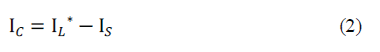
| The shunt part of the UPQC is known as distribution static compensator (DSTATCOM), and it is used to compensate load reactive power, harmonics and balance the load currents thereby making the source current balanced and distortion free with unity power factor [9]. Voltage rating of dc-link capacitor largely influences the compensation performance of an active filter.Shunt active filter maintains the voltage across the dc link capacitor bank. In order to cancel the harmonics generated by a nonlinear load, the shunt inverter should inject a current given by the following equation | ||||||||||||||||||||
 |
||||||||||||||||||||
| Where IC, I*L, and ISrepresent theshunt inverter current, reference load current, and actualsource current, respectively.Thus UPQC improves the power quality by preventing load current harmonics and by correcting the input power factor. The main components of a UPQC are series and shunt power converters, DC capacitors, low-pass and high-pass passive filters, and series and shunt transformers The main purpose of a UPQC is to compensate for supply voltage power quality issues, such as, sags, swells, unbalance, flicker, harmonics, and for load current power quality problems, such as, harmonics, unbalance, reactive current, and neutral current [14]. | ||||||||||||||||||||
PROPOSED SYSTEM CONFIGURATION |
||||||||||||||||||||
| The proposed system configuration of UPQC along with its control circuits for 3 phase 4 wire system is shown in fig.2. Here Vsa, Vsb and Vsc represent the source voltages for all the 3 phases, Rs and Ls represents the source resistance and inductance respectively, Vt represents the terminal voltage, Vdvra, Vdvrb, Vdvrc represents the voltage injected by series active filter for the 3 phases a, b and c respectively. Cse, Lse and Rsw represent the capacitor, inductor and resistor in the filter circuit of the series active filter. The filter circuit protects the series active filter from fault current and high voltage surges; also it is used to filter the ripples in the waveform. Vla, Vlb and Vlcrepresent the load voltage. The interfacing inductance and resistance of the shunt active filter are represented by Lf and Rf respectively. Cf represents the capacitor that is connected in series with the shunt active filter. | ||||||||||||||||||||
| In this topology UPQC is connected between source and load. Here a combination of linear and nonlinear load is connected to the source. The shunt active filter and series active filter composed of 3 legged IGBT switches as shown in fig 2. Here a capacitor Cf is connected in series with shunt active filter, which helps to reduce the voltage rating of dc link capacitor. The neutral is connected to the negative terminal of the dc link capacitor. Thus the output voltage of shunt active filter has only positive dc voltage across the dc link capacitor, which helps to maintain the voltage required for compensating for the reactive power drop and voltage sag [15]. Under balanced condition, the voltage and current in all the phases are uniform. Thus positive sequence components alone will be there. When a fault or an unbalance occurs, negative and zero sequence components will be there. The zero sequence components will cause zero sequence current to flow through the neutral terminal. Since the neutral is grounded via the negative terminal of dc link capacitors, the neutral current is eliminated and the unbalanced condition is cleared by injecting the required voltage to the phases by the UPQC by sensing the abnormal condition with the help of sensors and controllers. | ||||||||||||||||||||
CONTROL STRATEGY |
||||||||||||||||||||
| The compensation performance of shunt and series active filter depends on the turning on and turning off of semiconductor switches used in shunt and series active filter respectively.Hysteresis band current control scheme is used to generate gate pulses for VSI switches. In a hysteresis controller the reference compensation current is compared with the actual current that is being injected by the compensation circuit. Hysteresis current controller scheme is based on a feedback loop, generally with two level comparators. The switching commands are issued whenever the error limit exceeds a specified tolerance band “±h” [15]. Where ‘h’ is the hysteresis band limit. Hysteresis voltage limit is set for series active filter and hysteresis current limit is set for shunt active filter. Whenever the limit is violated triggering pulses for appropriate switches for both series and shunt active filter were supplied by the hysteresis controller. | ||||||||||||||||||||
| The voltage source inverters are supplied from a common dc link capacitor. For the successful operation of the UPQC, the dc capacitor voltage should be at least 150 % of maximum line-line supply voltage.To regulate the capacitorvoltage constant, and for achieving load compensation or harmonic current compensation, controllers are used. PI controller has been used effectively to control the operation of UPQC over a long period. Nowadays intelligent controllers such as fuzzy logic controllers were preferred due to their advanced controlling capability [16]. These controllers are used to trigger the semiconductor switches used in both voltage source inverters. Controllers give firing pulses in order to turn on the switches at proper intervals of time for achieving power quality enhancement. When the capacitor voltage falls below a particular value switches are turned on to energize the capacitor, so that the voltage required for achieving load compensation and voltage regulation has to be maintained at all periods of time. The sensed DC link voltage Vdc is compared with a reference voltage V*dc. The error signal obtained is processed in fuzzy logic controller. The output of the fuzzy logic controller is used to generate a 3 phase reference current by comparing load current as shown in fig 2. | ||||||||||||||||||||
| Series active filter maintains balanced, sinusoidal, distortion free nominal voltage at the load. Series active filter injects voltage through series transformer when a voltage drop occurs. The series active filter is controlled in such a manner that it injects voltage (Vdvra, Vdvrb, Vdvrc) in order to cancel out the distortions present in the supply voltage Vsa, Vsb, Vsc) thus making the voltage at the PCC (Vla, Vlb, Vlc) perfectly sinusoidal with desired amplitude. In other words, the sum of supply voltage and the injected series filter voltage makes the desired voltage at the load terminals. In this topology source voltages and load voltages are sensed and compared so as to obtain a reference voltage for the phases a, b and c. The reference voltage is used to generate 3 phase reference current using 3 phase reference current generator. The reference current thus produced is fed to hysteresis current controller. The hysteresis controller generates gate pulse for series active filter by comparing the reference current and voltage injected by series active filter. | ||||||||||||||||||||
FUZZY LOGIC CONTROLLER |
||||||||||||||||||||
| Fuzzy logic controller eliminates the draw backs of PI controller. The difficulty with PI controller is that it is a feedback system, with constant parameters, and no direct knowledge of the process. Fuzzy logic is close in spirit to human thinking and natural language. It provides an effective means of capturing the approximate and inexact nature of systems. The fuzzy control is basically a nonlinear and adaptive in nature, giving the robust performance in the cases where in the effects of parameter variation of controller is present. Fuzzy control system is a control system based on fuzzy logic, a mathematical system that analyses along input values in terms of logical variables that take on continuous values between 0 and 1. Controllers based on fuzzy logic give the linguistic strategies control conversion from expert knowledge in automatic control strategies [19]. Basic block diagram of a fuzzy logic controller is shown in fig 3. | ||||||||||||||||||||
| In the fuzzy control scheme, the operation of controller is mainly based on fuzzy rules, which are generated using fuzzy set theory. Fuzzy controller plays an important role in the compensation of power quality problems. The steps involved in fuzzy controller are fuzzification, decision making, and defuzzification. In fuzzification process the crisp values of the converter input is converted into fuzzy values using fuzzy rules [17]. The fuzzification process has no fixed set of procedure and it is achieved by different types of fuzzifiers. The shapes of fuzzy sets are triangular, trapezoidal and more. Here, a triangular fuzzy set is used. The fuzzified output is applied to the decision making process, which contains a set of rules [18] [19] [21]. Then, the defuzzification process is applied and the fuzzified calculated voltage (Vdc) is determined. The structure of designed fuzzy logic controller is illustrated as shown in fig 4. | ||||||||||||||||||||
| The steps for designing fuzzy controllers are fuzzification strategy, data base building, rule base elaboration, Interface machine elaboration and Defuzziffication strategy. | ||||||||||||||||||||
SIMULATION RESULTS AND DISCUSSIONS |
||||||||||||||||||||
| The theoretical design of the proposed UPQC system for 3 phase 4 wire distribution systems is to be verified mathematically in order to validate its performance. Therefore in order to validate the proposed topology, simulation is carried out using MATLAB/Simulink. The simulation diagram of the proposed system is shown in fig 5. | ||||||||||||||||||||
| A combination of linear and nonlinear load is connected to the source. Here the source voltage is taken as 240 V. As discussed in earlier sections, here 4 legged VSI based UPQC were used to enhance power quality. Scopes are connected at various points in order to estimate the results. The voltage across the dc link capacitor is taken as 560 V. In conventional system the voltage across the dc link capacitor was 1080 V [15]. The performance of the proposed system is evaluated in terms of voltage and current waveforms.The simulation results with the proposed modified topology are shown in figs. 6, 7, 8, 9, and 10. | ||||||||||||||||||||
| Fig. 6 shows the three phase source voltages for phase a, b and c. Fig. 7 shows the three phase load current for phase a, b and c. Observing the waveforms of figs 6 and 8, it is clear that UPQC effectively compensates for the voltage related power quality problems.The waveform is balanced and sinusoidal. | ||||||||||||||||||||
| Fig.8 shows the load voltages for all the 3 phases. The load voltage waveform is obtained from the point of common coupling. When a distortion occurs the UPQC compensates distortion in the current waveform by injecting the required current. The load current is nearly sinusoidal and balanced. The compensation performance is satisfactory. When an unbalance or fault occurs zero sequence current components appears in neutral. In this topology the neutral current is zero, since it is grounded. The controller in shunt active filter sense the unbalances and eliminates the disturbance by injecting required current to the load terminal. | ||||||||||||||||||||
| The voltage across the dc link capacitor in the proposed system is taken as 560 V. Therefore the voltage at the ac side of the series and shunt active filter varies between +560 V and -560 V as shown in figs 9 and 10. | ||||||||||||||||||||
| Fig 9 and 10 shows the voltage across across each legs of shunt and series active filters. The shunt active filter requires a higher voltage rating across the dc link capacitor. Where as the series active filter requires a lower voltage rating across dc link capacitor. These variation is solved with the introduction of series capacitor Cf which is explained in [15]. The series capacitor carries the extra required voltage for shunt active filter. | ||||||||||||||||||||
| The average switching frequency is reduced in the proposed system. The switching loses is also reduced. The fuzzy logic controller maintains the voltage across the dc link capacitor at all period of time. From the above simulation results it is clear that the proposed UPQC topology with fuzzy logic controller is capable of mitigating voltage and current related power quality problems simultaneously in the distribution system. | ||||||||||||||||||||
CONCLUSION |
||||||||||||||||||||
| An advanced design of UPQC for a 3 phase 4 wire distribution systems is proposed in this paper. The proposed system has the capability to mitigate voltage and current related power quality issues with reduced dc link voltage rating. The fuzzy logic controller eliminates the draw backs of PI controller.MATLAB/Simulink shows the effectiveness of the proposed UPQC system.From the results, it is clear that the proposed UPQC system can compensate for voltage sag/swell, harmonics in voltage and current waveforms and reactive power, thereby making the load voltage balanced and sinusoidal. | ||||||||||||||||||||
Figures at a glance |
||||||||||||||||||||
|
||||||||||||||||||||
References |
||||||||||||||||||||
|


