Power line communication is a cost-effective, facile and reliable tool for the current electrical distribution grid and will play a significant role towards realizing smart grids in future. Low voltage electrical networks provide a harsh environment for data communication. Significant attenuation, noise, interferences, multipath reflections and overall unpredictable and time varying access impedance are some of the major problems faced by power line communication in its current state. The demand for smart greenhouses is rapidly increasing to meet the energy demand in future. So the need of an effective communication link between main grid and the residential grid is inevitable. This paper aims at removing one of the big hindrances in achieving power line communication, which is impedance mismatch between the communication system side and load side. Although there are many impedance matching techniques, a thorough comparison of all major techniques is required to find out which one is technically efficient and cost effective. It explains the performance variation in different system areas and therefore helps in providing better perceptive of power line communication in real applications
Keywords |
| Impedance matching, Coupling transformer,Narrowband power line communication (N-PLC) |
INTRODUCTION |
| Narrowband Power line communication or N-PLC refers to transferring data over power line in a restricted frequency
band of 3 KHz to 148.5 KHz. This band of frequency has been widely applied over the electricity distribution grid for
achieving home automation, automatic meter reading and many other applications. Through N-PLC all electrical
devices plugged into the main grid in a particular area, can have a common communication link by utilizing the same
power line, rather than using external wires and sensors. The performance of any PLC system generally depends on
time, location and power network wiring topology [8]. Power line provides a harsh environment for data transfer
including multiple reflections, interferences, noise and over all time varying access impedance. In such scenario
impedance matching between communication system and load plays a vital role in improving range of data
transmission and also maintaining appropriate signal strength. The power level of signal should also be within the limit
so that Electromagnetic Interference (EMI) through emissions will not exceed the levels allowed by regulations else the
energy burst will disturb the other wireless users in adjacent frequency bands [3]. If the transceivers and the channel
impedance can be matched, not only the signal power delivered from one node to another can be maximized, but also
signal reflections can be minimized. To be more specific, if the reactance in the channel is fully matched via a coupler,
the power efficiency can be increased dramatically. Therefore this paper aims at simulating and comparing different
schemes for impedance matching and coming up with a technically superior and cost effective design of impedance
matching. |
BRIEF OVERVIEW OF IMPEDANCE MATCHING |
| Impedance matching is the practice of designing the input impedance of an electrical load (or the output impedance of
its corresponding signal source) to maximize the power transfer or minimize reflections from the load. In this section
we briefly discuss what are the various standard impedance matching designs and schemes, and then a detail simulation
of each technique with their performance analysis is provided in the subsequent sections. |
| A. Basic Impedance Matching |
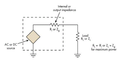
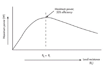
| The maximum power-transfer theorem says that to transfer the maximum amount of power from a source to a load, the
load impedance should match the source impedance. In the basic circuit, a source may be dc or ac, and its internal
resistance (Ri) or generator output impedance (Zg) drives a load resistance (RL) or impedance (ZL) as shown in fig. 1.
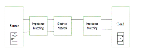
However in real time applications load and source impedance don’t match so we need to provide an impedance matching
circuit to achieve maximum power transfer from source as shown in fig. 1. |
| B. Impedance Matching in Power Line Communication |
| One of the major thrust areas in improving power line communication is impedance matching. Fig. 4 shows the basic
layout of power line communication and fig shows the change which needs to be made to improve the system. There
are various methods to match transceiver and access impedance either by using an external circuit to bring impedance
change or make changes in existing circuit to bring change. |
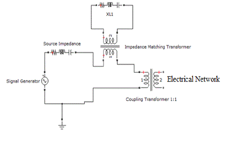
| 1. Impedance Matching using capacitor bank |
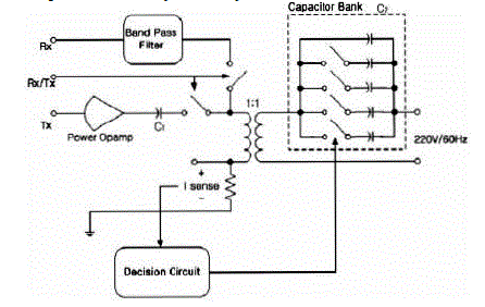
| In [4], authors describe a technique of measuring line impedance using the coupling circuit and the impedance
matching section consists of capacitive banks controlled by micro relays and a controller. As the line impedance is
mainly inductive so the arrangement shown in fig. 5 helps in achieving impedance matching up to certain limit but it
comes with its own disadvantages. As the capacitive bank is put on high voltage side after the coupling transformer of
communication system, the capacitors are costly and bulky. |
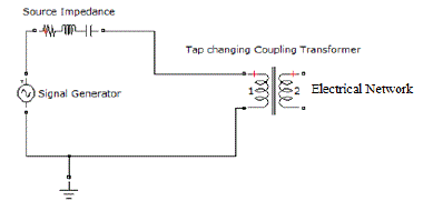
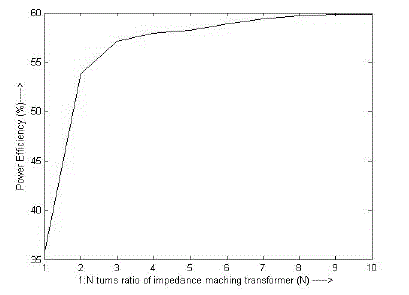
| 2. Impedance matching by using tap changing transformer with a particular impedance in its secondary |
| This particular design consists of an extra transformer before the coupling transformer which does the work of
reflecting a particular impedance on source side to match with the load side. This particular design has four variables
which can be controlled depending on the requirement. The variables are the turns ratio of the impedance matching
transformer, the resistance, the capacitance and the inductance connected to the secondary side of the transformer.
Although changing all the variables at a time to match impedance might be a tedious job but fixing three variables
appropriately and changing any one might prove advantageous. Also the secondary impedance of the impedance
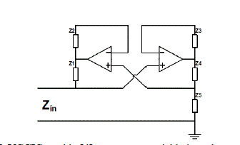
matching transformer can be changed by a voltage controlled general impedance converter. In [5], Park et al. comment
on previous work for adaptive impedance matching and point out that many external components such as capacitors,
switches and transformers increase the price and size of matching circuits. To address these problems, they suggest the
use of a Voltage Controlled General Impedance Converter (VCGIC), as shown in Fig. 7. |
SIMULATIONS AND RESULTS |
| Matlab and Simulink are used to create a similar environment for power line communication as it would see in real life
situation. The simulation scheme consists of a 230volt low voltage AC transmission line between the distribution transformer and residential units. The distance is assumed as 1Km (typically few hundred meters). The transmitter
circuit is a 130 KHz signal generator having a source impedance of 50ohms which is connected to a 230volt AC line
through a coupling capacitor. The receiver circuit similar to transmitter is placed near one of the house loads.
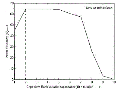
This analysis mainly aims at plotting the efficiency of the signal power transmitted and received. All the three cases of
impedance matching mentioned above are simulated and compared for finding the most efficient, easy and cost
effective method for achieving impedance matching. |
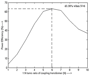
| From the above observation we can conclude that having a tap changing coupler can prove a technically efficient and
cost effective techniques for impedance matching in power line communication. |
CONCLUSION |
| Considering the above results we can conclude that a variable coupling transformer for the transmitter and receiving
circuit would prove really effective for impedance matching and maximum power transfer. As the parameters are
manually changed during simulation, efficiency could be increased only upto a certain limit. So the future work would
aim at achieving maximum efficiency by developing an adaptive control system which would match the impedance
dynamically by tuning the coupling transformer taps with reference to the access impedance. |
Tables at a glance |
 |
| Table 1 |
|
| |
Figures at a glance |
 |
 |
 |
 |
 |
| Figure 1 |
Figure 2 |
Figure 3 |
Figure 4 |
Figure 5 |
 |
 |
 |
 |
 |
| Figure 6 |
Figure 7 |
Figure 8 |
Figure 9 |
Figure 10 |
 |
 |
 |
| Figure 11 |
Figure 12 |
Figure 13 |
|
| |
References |
- Li Qi; She Jingzhao; FengZhenghe, "Adaptive impedance matching in power line communication," Microwave and Millimeter WaveTechnology, 2004. ICMMT 4th International Conference on, Proceedings , vol., no., pp.887,890, 18-21 Aug. 2004
- Araneo, R.; Celozzi, S.; Lovat, G., "Design of impedance matching couplers for power line communications," Electromagnetic Compatibility, 2009. EMC 2009. IEEE International Symposium on , vol., no., pp.64,69, 17-21 Aug. 2009.
- Yuhao Sun; Amaratunga, G., "High-current adaptive impedance matching in narrowband power-line communication systems," Power Line Communications and Its Applications (ISPLC), 2011 IEEEInternational Symposium on , vol., no., pp.329,334, 3-6 April 2011.
- Won-Ho Choi; Chong-yeon Park, "A simple line coupler with adaptive impedance matching for Power line Communication," Power Line Communications and Its Applications, 2007. ISPLC '07. IEEE International Symposium on , vol., no., pp.187,191, 26-28 March 2007
- Chong-Yeun Park; Kwang-Hyun Jung; Won-Ho Choi, "Coupling circuitary for impedance adaptation in power line communications using VCGIC," Power Line Communications and Its Applications, 2008. ISPLC 2008. IEEE International Symposium on , vol., no., pp.293,298, 2-4 April 2008
- Taherinejad, N.; Rosales, R.; Mirabbasi, S.; Lampe, L., "On the design of impedance matching circuits for vehicular power line communication systems," Power Line Communications and Its Applications (ISPLC), 2012 16th IEEE International Symposium on , vol., no., pp.322,327, 27- 30 March 2012
- Van Rensburg, P.A.J.; Ferreira, H.C.; Snyders, A.J., "Coupler Winding Ratio Selection for Effective Power Transfer to a Power-Line Communications Receiver," Power Line Communications and Its Applications, 2006 IEEE International Symposium on , vol., no., pp.290,295, 0-0 0
- Yasser Fathi; Tamer A. Kawady; Ahmed Husein; Mohamed El-Geziry, âÃâ¬ÃÅPractical Issues of Power Line Communication for Automatic Meter Reading SystemsâÃâ¬Ã Proceedings of the 14th International Middle East Power Systems Conference (MEPCONâÃâ¬Ãâ¢10), Cairo University, Egypt, December 19-21, 2010, Paper ID 252.
- M.KatayamaT.Maenou, "Study on signal attenuation characteristics inpower line communications," 2006 IEEE International Symposium on Power Line Communications and Its Applications, pp. 217 - 221, October 2006.
- H. Li Y. Sun F. Jia, "Application of power line communication to the home network," 2008, 11th IEEE International Conference on Communication Technology, pp. 521 - 524, Nov. 2008.
|