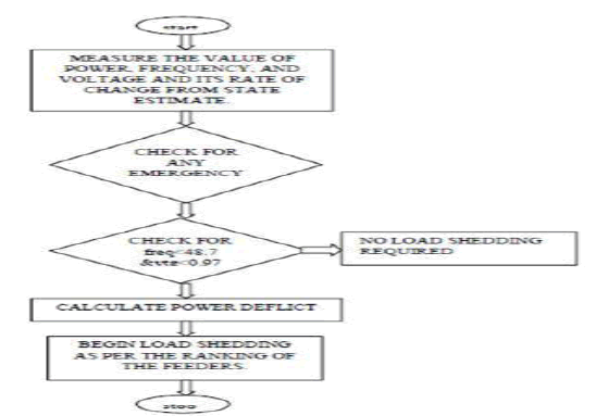
The safe operation of electrical power systems is an on-going problem. Despite the existing defence lines in the different electrical systems, they are not immune to widespread incidents leading to tripping of most customers. In the defence plans against these major incidents, selective load shedding, even optimized but brutal, is the last resort before total shutdown. This paper addresses a new power system control strategy from customer’s perspective. Due to power deficit we’ve to shed some amount of loads eventually. Now the main challenge is to determine the minimum load amount for shedding so that we can maximize the electricity supply to customers. Using control algorithm we’ll find out that minimum amount of load.
Keywords |
| Minimum Load, Control Algorithm, Power Deficit |
INTRODUCTION |
| During power deficit, one of the main operator’s tasks is to keep as many customers on-line as possible. The rise in
need is very steep for the reasons of rise in electrical utility appliances which is now the order of the day. So the
developing countries where there is free market cannot ration the usage of electrical appliances. This has steeply
increased the necessity. The efficient load shedding means to improve power system stability, by providing a real time
adapted load control and load shedding, in situations where the power system otherwise would go unstable. The main
aspects are evaluating the right amount and location of power response for a given disturbance and evaluating the right
time response expected in order to comply with the acceptable stability recover. Blocking can be viewed as if the power
exchanges were not controlled. Some lines located on particular paths may become overload and this phenomenon is
called blocking. Blocking management can be defined as the quick operations taken by the technical persons to relieve
the problem. One such approach is efficient load shedding. If excessive load shedding in the system is done, there will
be sudden change in the system voltage profile that causes transients in the system. |
FUNDAMENTALS OF LOAD SHEDDING |
| The data’s from the substation are taken and with these an idea for optimum load shedding is arrived using different
standard algorithm. The below are the conventional load shedding methodologies followed by the utility providers. |
| 1. Breaker Interlock Load Shedding |
| This is the simplest method of carrying out load shedding. For this scheme, the circuit breaker interdependencies are
arranged to operate based on hard wired trip signals from an intertie circuit breaker or a generator trip. This method is
often used when the speed of the load shedding is critical. Even though its execution is fast but it has few drawbacks. |
| 2. Under Frequency relay Load Shedding |
| Guidelines for setting up a frequency load shedding are common to both large and small systems. Upon reaching the
frequency set point and expiration of pre-specified time delay, the frequency relay trips one or more load breakers. This
cycle is repeated until the system frequency is recovered. e.g., 10% load reduction for every 0.5% frequency reduction. |
| 3. Programming based Load Shedding |
| With a programmable logic controller scheme, load shedding is initiated based on the total load versus the number of
generators online or detection of under-frequency conditions. Each substation PLC is programmed to initiate a trip signal to the appropriate feeder breakers to shed a preset sequence of loads. This static sequence is continued until the
frequency returns to a normal, stable level. |
PROPOSED METHODOLOGY |
| Till now there is no standard load shedding methods implemented in Bangladeshi power grid operations. Decision for
load shedding will be taken using conventional power flow calculations at centralized load centres and it will be
communicated to local or sub load centres where it will be implemented. The load shedding scheme mainly has
included the measurements of important parameters for estimating the magnitude of disturbance. The initial estimation
of the disturbance is based on the rate of change of frequency. The location of load to be shed and the amount to be
shed from each bus is calculated by the empirical formula. Here we’ll use Fuzzy Logic as control algorithm to find out
the minimum load amount to be shed. |
PROCEDURES FOR LOAD SHEDDING |
| o The data’s which are responsible for system transients are collected firstly. For our consideration, the data’s
from Rampura substation is collected and used for load shedding. |
| o The ranges of voltage, frequency, power is taken here. |
| o After the data’s are collected it is converted to per unit basis, if it not so. |
| o Create a table and enter the values of voltage, frequency, power. |
| o The value of reactive power is considered here. |
| o Now change in voltage and frequency with respect to time is calculated for calculation purpose. |
| o The amount of load shedding is calculated by using the formula, |
| S= ((dv/dq) / (Σ dv/dq)) pdiff. |
| Where, |
| S= load to be shed. |
| dv = change in voltage w.r.t time. |
| dq = change in power w.r.t time. |
| Pdiff= power difference. |
| To calculate the pdiff value, Pdiff= (2H/fo) (df/dt). |
| Where, |
| H= inertia constant (5sec). |
| fo= nominal frequency |
| o After calculation the amount of load to be shed is known. Now a new column in which load to be shed and in
another the pdiff values are entered. |
| o From the table the minimum and maximum ranges of values of each variable is calculated to create the
membership function. |
| o Now membership function is created for voltage, frequency, pdiff, reactive power by dividing the ranges into
3 categories, for simple calculation. |
| o Membership function for this consideration is LOW, MEDIUM, HIGH. |
| o Find the corresponding values in table. |
| o Create rules based on membership function. (if-then rule) |
| o Create a fuzzy linguistic control table. |
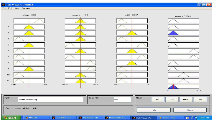
| o Apply the values in fuzzy MATLAB software and create the rules from the table. |
| o It must be noted that the rules which we create must radios must satisfy all the values within given range |
| o For our given value the amount of load shed is displayed |
| o Now if we compare the output with the conventional methods of load shedding it will be minimum only. |
MEMBERSHIP FUNCTION CREATION |
| Let each variable and the load shedding amount, s, be distinguished by three linguistic terms: LOW (L), MEDIUM
(M), HIGH (H). After analysis and from observation, the following linguistic rules describing the load-shedding
amount at substation can be formed. The membership function is created by considering the min and max ranges of the
variables and dividing each into 3 equal values and classifying each by the name low, medium, high as we mentioned
earlier. |
 |
MEMBERSHIP FUNCTION CREATION |
| Let each variable and the load shedding amount, s, be distinguished by three linguistic terms: LOW (L), MEDIUM
(M), HIGH (H). After analysis and from observation, the following linguistic rules describing the load-shedding
amount at substation can be formed. The membership function is created by considering the min and max ranges of the
variables and dividing each into 3 equal values and classifying each by the name low, medium, high as we mentioned
earlier. |
| The range of voltage value is selected and the membership function is created within that range by dividing the
difference value of max and min value by 3. Now the value is added with the least (min) value to find the first
membership function. With the first membership value the divided value is again added to form the second membership
function and so on. Now the logic table considering range in the table for above data. |
 |
CONCLUSION |
| From the comparison it is clear that fuzzy scaling of critical parameters and writing the fuzzy linguistic rules properly,
has clearly given food results. The amount of load to be shed is minimized. This method has been developed from the
data’s obtained from the substation and the discussions with the field engineers. It is a logical thought by some ways
and means the load shedding has to be minimized. Even though load shedding is the last resort and practically followed
method to relieve blocking, there is a constant urge both from field engineers and academic circle to analyze and find
some ways to minimize the load shedding. In that regard this work can be respected. By building robust electronics in
such a Way that the fuzzy outputs are tuned to an fuzzy controller which is again governed by another control device
with feedback system and data acquisition system to monitor the bus parameters, when this forms a robust loop, this
idea can be tested and if the results are satisfactory this can be implemented in distribution substations. |
Tables at a glance |
 |
 |
 |
 |
| Table 1 |
Table 2 |
Table 3 |
Table 4 |
 |
 |
 |
 |
| Table 5 |
Table 6 |
Table 7 |
Table 8 |
 |
 |
 |
| Table 9 |
Table 10 |
Table 11 |
|
References |
- âÃâ¬ÃÅMicrosoft StreamInsight.âÃâ¬Ã [Online]. Available: http://msdn.microsoftcom/en-us/library/ee362541.aspx
- Ross, T. J., âÃâ¬ÃÅFuzzy Logic with Engineering ApplicationsâÃâ¬ÃÂ, second edition, John Wiley and Sons, Ltd, West Sussex, England, 2004.
- Thompson J. G., and B. Fox, "Adaptive Ioad shedding for isolated power sfiem.3," 1EEProc.-Gener. T r a m. Distrib.,VoI. 141, No. 5, pp. 491-496, Sep 1994.
- Vladimir V. Terzija," Adaptive Under- frequency Load Shedding Based on the Magnitude of the Disturbance Estimation", IEEE TRANS. ONPOWER SYS., VOL. 21, NO. 3, AUG. 2006.
- Yong Zheng and N. Chowdhury, âÃâ¬ÃÅExpansion of Transmission systemsin a deregulated environmentâÃâ¬ÃÂ, IEEE Canadian Conference on Electricaland Computer Engineering, Vol.4, May 2-5, 2004, pp.1943-1947.
- Yong Zheng and N. Chowdhury, âÃâ¬ÃÅExpansion of Transmission systems in a deregulated environmentâÃâ¬ÃÂ, IEEE Canadian Conference on Electricaland Computer Engineering, Vol.4, May 2-5,2004, pp.1943-1947.
|