The increase in power demand and limited sources for electric power has resulted in the existence of microgrid. Microgrid is a complex interconnected system which comprises of reactive power compensators nearer to the load and are used to operate the power system closer to the limits of stability. Reactive power support groups reduce voltage instability which is mainly associated with reactive power imbalance. Bus loadability also depends on the reactive power support that the bus can receive from the system. The serious type of voltage instability is voltage collapse which will lead to the complete blackout. Voltage collapse can be effectively prevented by reducing or by adding reactive power support prior to the point of voltage collapse. Locations of the reactive power compensators is the challenging task since in a multi bus system voltage collapse may occur in any bus. This paper focuses on the determination of the effective locations of reactive power compensators in the distribution system and also to analyze how the compensators connected at those buses are controlled. Hybrid approach is used for grouping the buses across which reactive support has to be provided. Voltage fluctuations get eliminated in the distribution grid through end user reactive power capable devices. The ability to provide real and reactive power support can be achieved at the end-user level itself.
Keywords |
| Microgrid, voltage collapse, reactive power compensators, distributed generation |
INTRODUCTION |
| The world is facing severe energy crisis and it is expected to increase in the forthcoming years. Worldwide, the
power generation is majorly done using conventional energy sources and its energy reserve is very much limited,
expected to disappear after few decades. The shortage of conventional energy resources and the necessity to reduce the
environmental impact have led to significant interest in renewable energy resources and their efficient utilization [1-2].
Hence there is a renewed interest in the power generating technologies based on renewable energy resources as it is
everlasting and eco-friendly. The only means to increase the generation capacity is by increasing the renewable energy
generation. Distibuted Generation (DG) is the group of renewable energy sources connected in parallel.One important
application of smart grid technology is microgrid, which comprises of DG systems. |
| In the recent years power systems are operated under many stressed conditions such as the use of new
technologies, bulk power transmissions, over long transmission lines, environmental pressures on transmission
extension, increased electricity use in profound load areas, new system loading patterns due to the opening up of the
electricity market, growing use of induction machines, and large penetration of wind generators and local
uncoordinated controls in systems. Under these stressed conditions a power system stability becomes a major concern
.Many major blackouts are caused due to power system instability. After analyzing the various blackout causes, it was
noted that cascading failures may occur due to the loss of generation units, breaker failures, common tower and
common right-of-way circuit outages, combination of system conditions and events. The main factor causing instability
is the inability of the power system to meet the demand for reactive power. The major cause of voltage instability is the
voltage collapse. The only way to save the system from voltage collapse is to reduce the reactive power load or add additional reactive power prior to reaching the point of voltage collapse. Voltage collapse is a process whereby voltages
gradually refuse until it is no longer possible to maintain steady operating voltages. DG’s like PV cells, hybrid vehicle
connected nearer to the load acts as reactive power compensators. |
| Overbye in [9],[10] used damped Newton method for convergence for restoring system stability during severe
contingency. Linear approximation method is used to locate the power system solvability boundary in [11] for fast
occurrence of faults. Granville in [12] used the direct interior point method for computing minimum load shedding to
restore the power flow solvability. Wang et al.in [13] applied the direct interior point method to solve corrective control
problems. Also the present work have the control in substation level and corrective control is mostly discussed. |
| This paper presents the idea to mitigate the voltage collapse with the available reactive power resources in the
residential level devices as preventive control. The occurrence of voltage violations in the residential level devices are
eliminated with the help of the reactive power resources. Suppose when a problem is detected in the distribution
system, the particular low voltage buses are identified and it is reduced or eliminated with the help of the reactive
power resources in order to restore the system voltages. The available reactive power resources can be used to
compensate the voltages and thus make the system less susceptible to voltage instability. Corrective control and
preventive control are possible, among which preventive control is better since it restores the system voltage before it
actually occurs. Generally voltage violation in the load is corrected by the command received from the Central
Management Unit (CMU). But here a method is proposed in which the load voltage violations are met by the end user
reactive power compensators. Reactive power controlled buses need to be identified for effectively placing reactive
power compensating devices. Based on the sensitivities and voltage optimization problem the target of identification
and location of reactive power compensators are achieved. |
FLOW CHART |
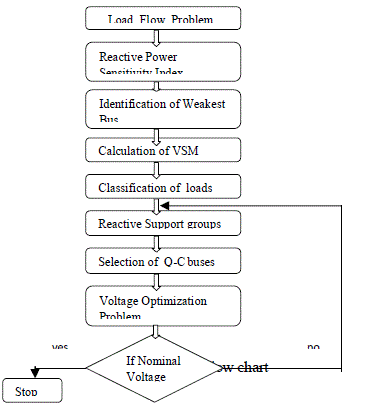
| The work flow is given in figure 1. The detailed description is given in the following subsections. |
| The objective function of the voltage optimization problem is to minimize the cost function f1 given by
equation 1 . |
 |
| where, n is the number of bus voltages to be controlled. To carry out this optimization problem primarily load flow
analysis has to be done. Voltage, real and reactive power flow at various buses is calculated. Newton Raphson method
is chosen in this work which has powerful convergence characteristics when compared to other methods. The aim of
solving this objective function is to determine the amount of reactive power compensation to be provided so as to
maintain the voltage profile within bounds. |
| (ii)Sensitivity index and Voltage Stability Margin(VSM) |
| Sensitivity index defines the reactive power injections which have high impact on the voltage. This index
evaluation is the basis for determining the location and amount of reactive power to be compensated. Real and reactive
power from load flow analysis is given by equation 2. |
 (2) (2) |
| Where, |
 |
| Jacobian matrix J2 and J3 can be set to zero because real power and reactive power are less sensitive to voltage and
phase angle respectively. Strongest bus and weakest bus are identified from maximum and minimum value of J4. P-V
and Q-V curves are plotted for identifying voltage collapse point. Voltage collapse point is the point after which load
flow problem will not be converged. |
| Voltage Stability Margin of a power system is the measure to estimate the available power transfer capacity
and it defines the security level of the bus. VSM is defined as the difference or ratio between the bus voltage at normal
operating point and Voltage Collapse Point(VCP). |
 (3) (3) |
| VWbase , VWcritical = bus voltage of the system at normal operating condition and voltage collapse point. |
| (iii)Classification of loads and reactive power controlled (Q-C)buses |
| Selection of reactive power controlled buses requires the additional information on classification of load
buses. Load buses can be classified based on its controllability of reactive power as most controllable bus and noncontrollable
bus. Controllable bus is described as CAT1 (category 1) and non-controllable bus is described as CAT2
(category 2). The slack bus and the PV buses are considered as CAT2 buses since their reactive power cannot be
controlled. Buses with zero reactive power can also be categorized as CAT2.The PQ buses are considered as CAT1.
Partially controlled and priority in which buses can be controlled are not considered in this paper. |
| Buses with higher sensitivities are identified as the members Q-C buses. Buses with lower values will have no
control over voltage when reactive power is varied. So, they are not considered as reactive power controlled bus.
(iv) Reactive power support groups |
| Buses are to be grouped to control the voltage by adjusting the reactive power. Various algorithms are
described for grouping the buses. Hybrid approach is used in this paper. |
| (a)Hierarchical Clustering Algorithm |
| In this method buses are grouped based on hierarchy. Either bottom-up approach or top-down approach is followed
which is named as agglomerative hierarchical clustering algorithm or divisive hierarchical clustering algorithm
respectively. Agglomerative hierarchical algorithm is adopted in this paper. |
| Each element in the J4
-1 matrix is considered as a single cluster and closest elements are merged. At the
highest level all the elements are clustered into single cluster. Agglomerative clustering depends on the use of a
distance matrix D. Elements Dij gives the distance between row i and j of J4
-1.From the distance matrix pair of clusters
with the shortest distance are merged. The shortest distance pair is then removed from the matrix and both are merged.
All distances are evaluated and new clusters are formed and the process is repeated until the distance matrix is reduced
to a single element. |
| (b)Voltage Coupling Index (VCI) Algorithm
An index called as voltage Coupling Index (VCI) is used to describe the ability of line flows and also be used to
control the voltages by reactive power injections. Buses are grouped based on the sensitivity of reactive power
generations to reactive power demands. |
 |
| where, SG represents the sensitivity of reactive power generations to voltage magnitudes at load buses
SL represents the sensitivity of reactive power demands to voltage magnitudes at load buses. |
| Elements of matrix [S] represent sensitivity of reactive power generations to reactive power demands. Load buses with
closer reactive power sensitivity values have been merged together to form voltage control areas. |
| (c)Hybrid Approach |
| Hybrid approach combines the algorithms and it is the efficient approach for identifying the reactive support
groups. |
RESULTS AND DISCUSSION |
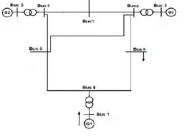
| IEEE 9 bus system is considered for the simulation. The single line diagram for IEEE 9 bus system is shown
in figure 2. The line and bus specifications are given in table 1 and 2. |
| The sensitivity values of the buses are estimated from jacobian matrix and are tabulated in table 3 |
| Weakest bus is identified from the sensitivity values. 5th bus is identified as the weakest bus and 9th bus is
identified as the next weakest bus. |
| The Q-V curve and the P-V curve are plotted for both the buses to identify the Voltage Collapse Point(VCP).
Q-V curve is plotted by keeping real power as constant and increasing reactive power till knee point occurs. Similarly
P-V curve is drawn for constant reactive power. Figure 3.1 and 3.2 shows the Q-V curve for bus 5 and 9. Figure 4.1 and
4.2 shows the P-V curve for bus 5 and 9. |
| VCP is identified for both the buses from the Q-V and P-V curves and VSM as calculated using equation 3.
The values are tabulated in table 4. The loads are classified as CAT1 and CAT2 as explained and it is shown in table5 |
| Based upon the hierarchical clustering algorithm and voltage coupling index algorithm the reactive support groups are
identified and the various groups are tabulated in table 6. Reactive power support is provided for all the combinations
as listed in table 6 and the sensitivities and the voltages are listed in table 7. |
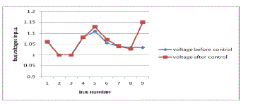
| Q-C bus 8-9 is selected as the effective location for placing reactive power compensator since the minimum objective
function is obtained for that combination. The reactive power compensation is provided between buses 8-9 and voltage
profile is plotted for all the buses. Figure 6 shows the voltage profile of all the buses. |
| It is clear from the figure that the voltage profile is improved for the weakest bus as well as for the other buses
after compensation is provided. |
CONCLUSION |
| This paper presents a method for effectively locating reactive power compensator in the smart grid. Coordination
of multiple reactive power devices is allowed near the local loads. When local load voltage deviates from the
nominal value command from the central control unit is not required. Without any communication link voltage
deviation is rectified by proper addition or removal of reactive power. The objective of restoring the voltages by
effective placement is achieved. |
| Restoration of system voltages is the prime objective, but this can be efficiently applicable for any power
system crisis in which the distributed compensators will respond quickly. Constant loads are considered at present and
the work can be extended for dynamic loads in future. |
Tables at a glance |
 |
 |
 |
 |
| Table 1 |
Table 2 |
Table 3 |
Table 4 |
 |
 |
 |
| Table 5 |
Table 6 |
Table 7 |
|
| |
Figures at a glance |
 |
 |
 |
 |
 |
| Figure 1 |
Figure 2 |
Figure 3 |
Figure 4 |
Figure 5 |
|
| |
References |
- K. M. Rogers, R. Klump, H. Khurana, and T. J. Overbye, âÃâ¬ÃÅ Smart-grid-enabled load and distributed generation as a reactive resource,âÃâ¬Ã presented at the IEEE PES Conf. Innovative Smart Grid Technol., Gaithersburg, MD, Jan. 2010.
- Z. Feng, V. Ajjarapu, and D. J. Maratukulam, âÃâ¬ÃÅA comprehensive approach for preventive and corrective control to mitigate voltage collapse,âÃâ¬ÃÂIEEE Trans. Power Syst., vol. 15, no. 2, pp. 791âÃâ¬Ãâ797, May 2000.
- T. J. Overbye, âÃâ¬ÃÅComputation of a practical method to restore power flow solvability,âÃâ¬Ã IEEE Trans. Power Syst., vol. 10, no. 1, pp. 280âÃâ¬Ãâ287,Feb. 1995
- Angel A. Aquino-Lugo,RayKlump, and Thomas J. Overbye, Fellow, âÃâ¬ÃÅA Control Framework for the Smart Grid for Voltage Support Using Agent-Based TechnologiesâÃâ¬ÃÂ, IEEE Trans. Smart Grid vol. 2, no. 1, March 2011
- R. A. Schlueter, I.-P Hu, M.-W. Chang, J. C. Lo, and A. Costi, âÃâ¬ÃÅMethods for determining proximity to volt. collapse,âÃâ¬Ã IEEE Trans. Power Syst., vol. 6, no. 2, pp. 258âÃâ¬Ãâ292, Feb. 1991
- R. A. Schlueter, J. C. Lo, T. Lie, T. Y. Guo, and I. Hu, âÃâ¬ÃÅA fast accurate method for midterm transient stability simulation of voltage collapse in power systems,âÃâ¬Ã in Proc. 28th Annu. Conf. Decision and Control ,Dec. 1989, pp. 340âÃâ¬Ãâ344
- KabirChakraborty, Sangita Das Biswas,âÃâ¬ÃÅAn Offline Simulation Method to Identify the Weakest Bus and its Voltage Stability Margin in a Multibus Power networkâÃâ¬Ã Proceeding of International Conference,2010
- Overbye,,âÃâ¬ÃÅAn Authenticated Control Framework for Distributed Voltage Support on the Smart GridâÃâ¬ÃÂ, IEEE Transactions On Smart Grid,Vol.No.11,2010
- T. J. Overbye, âÃâ¬ÃÅA power flow measure for unsolvable cases,âÃâ¬Ã IEEE Trans. on Power Systems, vol. PWRS-9, pp. 1359âÃâ¬Ãâ1365, August 1994.
- T. J. Overbye, âÃâ¬ÃÅComputation of a practical method to restore power flow solvability,âÃâ¬Ã IEEE Trans. on Power Systems, vol. PWRS-10, pp.280âÃâ¬Ãâ287, February 1995.
- T. Van. Cutsem, âÃâ¬ÃÅAn approach to corrective control of voltage instability using simulation and sensitivity,âÃâ¬Ã IEEE Trans. on Power Systems,vol. PWRS-10, pp. 616âÃâ¬Ãâ622, May 1995.
- S. Granville, J. C. O. Mello, and A. C. G. Melo, âÃâ¬ÃÅApplication of interior point methods to power flow unsolvability,âÃâ¬Ã IEEE Trans. on PowerSystems, vol. PWRS-11, pp. 1096âÃâ¬Ãâ1103, May 1990.
- X. Wang, G. C. Ejebe, J. Tong, and J. G.Waight, âÃâ¬ÃÅPreventive/corrective control for voltage stability using direct interior point method,âÃâ¬Ã IEEE Trans. on Power Systems, vol. PWRS-13, pp. 878âÃâ¬Ãâ883, August 1998.
|