Plug-in hybrid electric vehicles (PHEVs) are connected to the electricity grid. The power flow of this connection can be either unidirectional or bidirectional, so vehicles can charge and discharge. This vehicle-to-grid option can aid to improve grid efficiency and reliability. Plug-in vehicles can behave either as loads or as a distributed energy and power resource in a concept known as vehicle-to-grid (V2G) connection. The use of electric vehicles (EVs, both purely electric and hybrid) which have to charge from the grid and may also inject power back to it in order to provide valuable services to ensure system stability and avoid congestion (“vehicle-to-grid”, V2G), is expected to grow. A scenario is provided that the market penetration of about 3.3 million EVs is achieved in 2020, increasing to 50 million EVs in 2030 (with a share of about 60% of these electric vehicles being PHEVs). Smart charging is assumed to become standard after 2020. The PHEV typically have a higher capacity onboard energy storage than a hybrid electric vehicle. This also offers reactive power support, active power regulation, and load balancing.
Keywords |
| Charging infrastructure, distribution system, grid operator, grid-to-vehicle (G2V), plug-in electric vehicles
(PEVs), regulation, smart charging, unidirectional/bidirectional power flow, utility interface, vehicle to- grid (V2G). |
INTRODUCTION |
| The V2G concept has attracted attention from grid operators and vehicle owners. PEVs can behave either as electric
loads or as generators. The charging behaviour of PEVs is affected by different factors, such as the type of connection
(unidirectional or bidirectional), geographical location, the number of PEVs being charged in a given vicinity, their
charging voltage and current levels, battery status and capacity, charging duration, etc.[1],[2]. Connection to the grid,
control and communication between vehicles and grid operator, and onboard/ off-board smart metering are required
for beneficial V2G operation [3]. A bidirectional V2G system is generally required to support energy injection back to
the grid [4]. Aggregators collect PEVs into a group to create a larger, more manageable load for the utility. These
groups can act as distributed energy resources to realize ancillary services and spinning reserves. Cooperation between
the grid operator and vehicle owners or aggregators is important to realize the highest possible net return. Many
researchers have investigated potential benefits and costs issues of V2G concepts [4]. V2G-capable vehicles offer a
possible backup for renewable power sources including wind and solar power, supporting efficient integration of
intermittent power production [8]. V2G systems can provide additional opportunities for grid operators, such as
reactive power support, active power regulation . |
V2G CONCEPTS AND REQUIREMENTS |
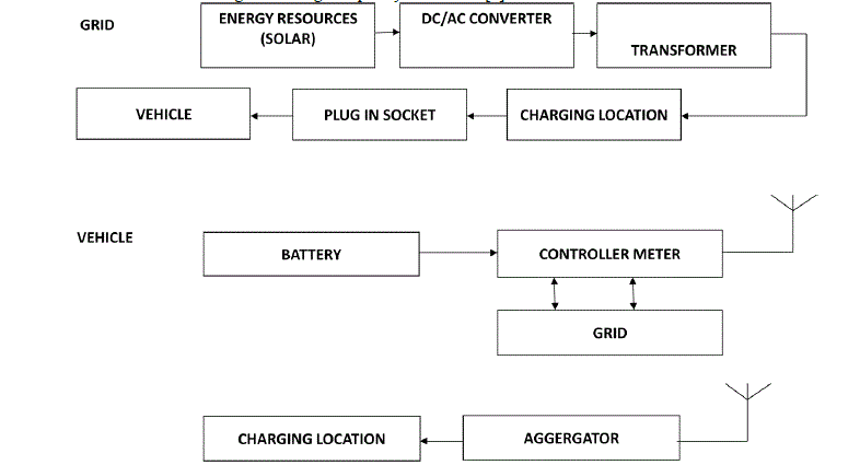
| The components and power flow of a V2G system are represented in Fig.1 . The system consists of six major
subsystems: 1) energy resources and an electric utility; 2) an independent system operator and aggregator; 3) charging
infrastructure and locations; 4) two-way electrical energy flow and communication between each PEV and ISO or
aggregator; 5) on-board and off-board intelligent metering and control; and 6) the PEV itself with its battery charger
and management. The concept requires three elements: a power connection to the grid, a communication connection
with the grid operator, and suitable metering; an efficient power transaction requires substantial information exchange
[10]. |
| Smart metering can make PEVs controllable loads and help combine PEVs and renewable energy. GPS locators and onboard
meters on charging stations can monitor and exchange information with the control center through a field area
network [3] . Plug-in hybrid electric vehicles have the opportunity to be combined with renewable energy. Renewable
energy, for instance photovoltaic and wind energy, has the property to be intermittent. In the ideal case, the renewable
energy and the generation by power plants should match the general consumption, which is the household and the
PHEV demand. Shock hazard risk reduction for PEV charging is addressed in, the standard for personnel protection
systems for PEV supply circuits [2]. Isolation is beneficial for PEV functions, including the high-voltage battery, dc–dc
converter, traction inverter and charger. Galvanic isolation is provided in electric vehicle supply equipment either with a
line transformer or dc converter stage with a high frequency transformer[3]. |
V2G POWERFLOW |
| Electricity flows from generators through the grid to electricity users. Electricity flows back to the grid from the
batteries in EV[1]. The control signal from the grid operator (ISO) could be a broadcast radio signal, a cell phone
network, or power line carrier. The grid operator sends requests for power to a large number of vehicles [7]. The
signal may go directly to each individual vehicle, to a fleet operator, or through a third-party aggregator to dispatch
power from individual vehicles. |
| 1) Unidirectional Power flow: |
| Power flow is bidirectional in general, as shown in Fig. 2. Unidirectional V2G, the basic battery
charge process, can provide services based on reactive power and dynamic adjustment of charge rates even
without reversal [2]. It requires no hardware other than an outlet and avoids extra EV battery degradation from
cycling. Properly designed unidirectional chargers can supply absorb reactive power by means of current phase
angle control. |
| 2) Bidirectional Power Flow |
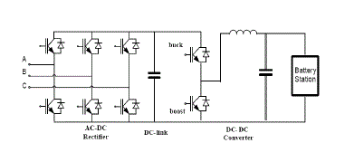
| A typical bidirectional charger has two stages: an active grid connected bidirectional ac–dc converter
that enforces active power factor correction, and a bidirectional dc–dc converter to regulate the battery charge or discharge current [5],. When operating in charge mode, the charger should draw a sinusoidal current with a defined
phase angle to control power and reactive power. In discharge mode, the charger should return current in a similar
sinusoidal form. |
CHARGING AND DISCHARGING |
| 1. Uncoordinated Charging/Discharging |
| Uncoordinated charging indicates that PEV batteries either start charging immediately when
plugged in or start after a user-adjustable fixed delay, and continue charging until they are fully charged or
disconnected [3],[4]. |
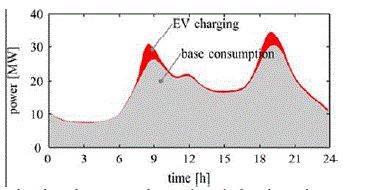
| The aggregated load in the simulated system is shown in Fig. 3, and peaks increase substantially. |
| 2. Coordinated Charging/Discharging |
| Coordinated smart charging and discharging can optimize time and power demand and reduce daily
electricity costs, voltage deviations, line currents, and transformer load surges[9]. Optimization of charging time
and energy flows reduces daily electricity cost with little effect on peak capacity needs. Incremental investments
and high energy losses can be avoided, and wasting renewable energy and network congestion prevented. |
RESULT AND DISCUSSION |
| The electric vehicle battery has been verified with the ability to inject power to the grid when necessary[1]. In this
case, the electric vehicle is working in discharging mode. |
| 1. Interaction between Distribution Grid and Charging Station |
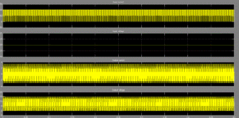
| The structure of the proposed electric vehicle charging station is made up of a full-bridge inverter/rectifier and a
DC-DC converter shown in Figure 3. The positive current direction is assumed to be from the grid to the inverter
as shown in Figure 4. So is the positive power flow direction [10]. |
| 2. Control of Bidirectional Buck–Boost DC-DC Converter |
| By changing the duty cycle of the DC-DC converter, both the charging current and charging voltage
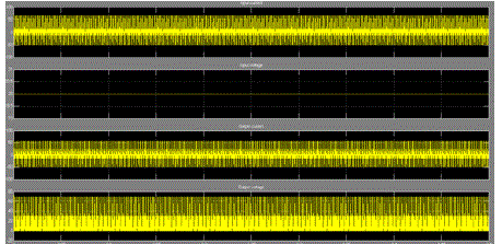
can be controlled accordingly [3]. Figure 4 and 5 correspondingly show the boost and buck outputs. |
| 3. Simulation Results |
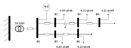
| In order to estimate the interaction between the distributed energy generator with electric charging station in
the proposed active distribution network,[7]. Case study is carried out in the chosen regional distribution network
as shown in Fig. 6 Charging stations are installed for those electric vehicles based on owner’s fast-charging
requirements. |
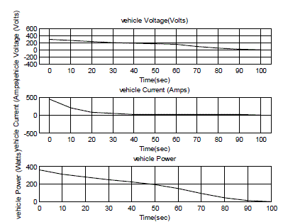
| Figure 8 show the voltage, current, and power profile measured at B1 in Case 1. At time 0.5s, three-phase
ground fault was applied at B2, and fault was cleared 0.1s later, a distinctive voltage dip can be observed from
Figure 7, where the fault is extremely severe such that the voltage falls below 0.15 p.u., which is below the limit
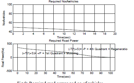
specified in the grid code issued by the UK National Grid Company[8] . The voltage limit specified by the Grid
Code, required number of vehicles and road power are shown in Figure 9. |
CONCLUSION |
| The impact of V2G technologies on distributed systems, and requirements, benefits, challenges, and strategies for
V2G interfaces of both individual PEVs and vehicle fleets were reviewed. Unidirectional V2G is a traditional and
logical first step because it limits hardware requirements, simplifies interconnection issues, and tends to reduce
battery degradation. A bidirectional V2G system supports charge from the grid, battery energy injection back to the
grid, and power stabilization.In the future work,the life of battery should be extended to a long extend and fast
charging is achieved. The simulation model for th electric vehicle battery and charging station is mainly developed
for power grid transient analysis. Further models will be needed for long term simulations where the charging cycle
and some other battery parameters should be considerate in the model. The simulation work was developed in
Matlab/Simulink, future simulation work will need to migrate to some other advanced power system simulation
software packages, with more rich DG simulation models and for large scale power grid simulations. |
Figures at a glance |
 |
 |
 |
 |
 |
| Figure 1 |
Figure 2 |
Figure 3 |
Figure 4 |
Figure 5 |
 |
 |
 |
 |
| Figure 6 |
Figure 7 |
Figure 8 |
Figure 9 |
|
| |
References |
- S. G. Wirasingha and A. Emadi, âÃâ¬ÃÅPihef: Plug-in hybrid electric factor,âÃâ¬Ã IEEE Trans. Veh. Technol., vol. 60, no. 3, pp. 1279âÃâ¬Ãâ1284, Mar. 2011.
- B. K. Sovacool and R. F. Hirsh, âÃâ¬ÃÅBeyond batteries: An examination of the benefits and barriers to plug-in hybrid electric vehicles and a vehicleto- grid transition,âÃâ¬Ã Energy Policy, vol. 37, no. 3, pp. 1095âÃâ¬Ãâ1103, 2009.
- M.Duvall and E.Knipping, âÃâ¬ÃÅEnvironmental assessment of plug-in hybrid electric vehicles. Volume 1: Nationwide Greenhouse Gas Emissions,âÃâ¬Ã EPRI/NRDC, Palo Alto, CA, Final Rep. 1015325, 2007, pp. 1âÃâ¬Ãâ56
- S. Rahman, âÃâ¬ÃÅMitigation of distribution level impact of electric vehicles,âÃâ¬Ã in Proc. Rec. IEEE Power Energy Syst. Innovative Smart Grid Tech. Conf., Jan. 2012.
- A. K. Srivastava, B. Annabathina, and S. Kamalasadan, âÃâ¬ÃÅThe challenges and policy options for integrating plug-in hybrid electric vehicle into the electric grid,âÃâ¬Ã The Electricity Journal, vol. 23, no. 3, pp. 83-91, Mar. 2010.
- L. Sanna, âÃâ¬ÃÅDriving the solution: The plug-in hybrid vehicle,âÃâ¬Ã Electr. Power Res. Inst. J., vol. fall, pp. 8âÃâ¬Ãâ17, 2005.
- S. V. Chakraborty, S. K. Shukla, and J. Thorp, âÃâ¬ÃÅA detailed analysis of the effective-load-carrying-capacity behavior of plug-in electric vehicles in the power grid,âÃâ¬Ã in Proc. Rec. IEEE Power Energy Syst. Innovative Smart Grid Tech. Conf., Jan. 2012.
- L. M. Brass, âÃâ¬ÃÅORNL Study Shows Hybrid Effect on Power Distribution, News Release, Oak Ridge National Lab., Oak Ridge, TN, Mar. 2008.
- D. P. Birnie, âÃâ¬ÃÅSolar-to-vehicle (S2V) systems for powering commuters of the future,âÃâ¬Ã J. Power Sources, vol. 186, pp. 539âÃâ¬Ãâ542, 2009
- K. R. Prakash, R. M. Soumya, and N. Kishor, âÃâ¬ÃÅDisturbance detection in grid-connected distributed generation system using wavelet and S-transform,âÃâ¬Ã Electr. Power Syst. Res., vol. 81, pp. 805âÃâ¬Ãâ819, 2011.
|