The implementation of the IEC61850-9-2 standard in substation automation systems requires the use of merging units for elimination of several multiple wire connections running from the switchyard to the microprocessor relays located in the control room. The conventional merging unit model collects current and voltage signals from various current and voltage transformers in the switchyard, converts them into digital form and sends the digital equivalents to the microprocessor relays via a single fiber optic cable known as the process bus. In this paper, we proposed a new merging unit model with additional features of in-built overcurrent protection and bay control functions. This new model is intended to provide local over-current protection and bay control for all equipments in the bay being monitored by a particular merging unit.
Keywords |
| Merging Unit, Substation Automation System, IEC61850, Process Bus. |
INTRODUCTION |
A. Related Works |
| Several research works have been done in the area of developing digital solutions for operation of automation systems
of substations. It was established in [1] that owing to the technological advancements in new communications
techniques, power substations are now being transformed from hardwired configurations to networked platforms in
order to achieve full automation of substations. Also, optical fiber communication technology has been identified as
the choice communication technique for the implementation of IEC 61850-8-1 and 9-2 standards for substation
automation [2, 3]. The fundamental concept of substation automation systems hinges on the possibility of using
microprocessor-based intelligent electronic devices (IEDs) to monitor and control equipments in a substation [1]. The
IEC 61850 standard combines the convenience of Ethernet communications with performance and security which are
essential for modern digital substations solutions as reported in [4]. Latest research works on realization of more
modern digital substations have largely been geared towards developing new process level equipments such as nonconventional
instrument transformers and intelligent switchgears that can communicate directly with the bay level and
station level of the substation with the merging unit working as the interfacing component between process level and
the bay level. |
B. Merging Unit Concept |
| The Merging Unit (MU) is one of the most critical elements required in the development of modern digital substations.
The MU provides the suitable interface for the implementation of the process bus concept in modern substation
automation systems. The IEC61850 standard specifies the communication architecture for communication systems and
networks for substations [5]. The basic function of the MU in automation systems is to convert the analogue values of
current and voltages measured at the process level to digital format and transmit same to the bay level of the substation
where the microprocessor relays are located. In modern substations, its function is to collect multichannel digital
signals output by electronic current and electronic voltage transformers synchronously and transmit these signals with
the protocol of IEC 61850 to protective, measurement and control devices [6]. |
SUBSTATION AUTOMATION USING IEC 61850 STANDARD |
| IEC 61850 Standard is becoming more widely used around the world wherever substation automation is to be put in
place. However, most of these conventional substation automation systems only utilize the capability of IEC 61850
related the communication between the bay level and station level of the system. Examples include communication
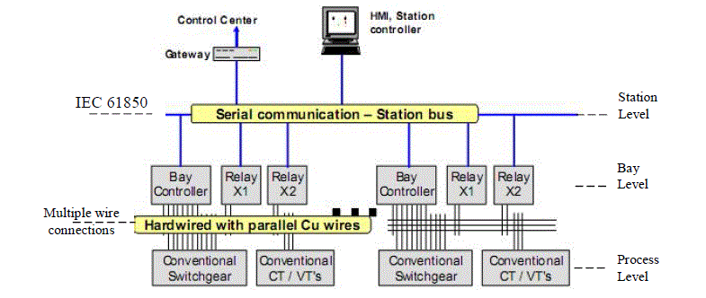
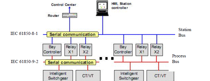
between protection relays, bay controllers, SCADA gateways and local HMIs as illustrated in figure 1. The possibility
of establishing direct communication up to the process equipments and intelligent switchgears according to parts 9-2
and 8-1 respectively of the IEC 61850 has so far been implemented in only some pilot installations. Thus the
destination of recent research efforts in substation automation systems is to move a step further from the state-of-the-art
conventional architecture to a fully digital substation in which the entire substation activities are realized through a
communication platform based on IEC61850. |
A. State of the Art Substation Automation System using IEC 61850 |
| Due to the exciting capabilities and technical benefits [4] the IEC 61850 Standard has introduced into substation
automation systems; it has received quite substantial patronage. As earlier mentioned and as illustrated in figure 1, the
state-of-the-art implementation of the IEC 61850 standard is limited to communication between the station level and
the bay level. In the conventional approach, the automation system of a substation consists of multiple IEDs e.g.
protection relays and bay control devices all connected to each other and to the substation gateway and local HMI
through a communication network by means of the station bus. It is called a station bus because it connects all the
devices of a substation. The protocol for the communication network is defined in IEC 61850-8-1 [5]. |
| However, communication between the bay level and the process level is still achieved by hardwired connections using
parallel copper wires. With this architecture, too many wired connections are required for connecting the process
equipments to the bay level devices. This is simply because each of the numerous signals that emanate from the
control, protection, and metering sections of the substation must be connected by a pair of copper wires which will run
from the process equipment all the way to the bay level devices in the control room. Thus wiring alone attracts huge
cost during installation of substations using the conventional architecture. |
B. New Communication Architectures for Substation Automation using IEC 61850 Standard |
| The need to achieve full automation of substation operation with reduced hardwired connections has led to the
extension of implementation of IEC 61850 up to the process level of substation automation. To achieve this, IEC 61850-9-2 is now being implemented at the process level such that process equipments like current transformers (CTs),
voltage transformers (VTs) and switchgears can now communicate directly with the rest the devices over a fiber optic
network. The automation system is realized with the introduction of another communication network known as the
process bus. This is illustrated in figure 2 [8]. In figure 2, the multiple hardwired connections (as in figure 1) are
replaced with a single fiber optic cable forming a complete Ethernet substation LAN. |
| In this automation system architecture, the process equipments are made to include intelligent devices which can be
directly interfaced to the communication system. |
| However the functionality of the intelligent devices depends largely on the technology of the primary equipment. The
minimum specification is that each of the process equipment must include a communication interface according to the
IEC 61850 Standard. |
| One of the techniques used is to connect the switchgears (circuit breakers and isolators) to the process bus via remote
I/O devices which are directly connected to the communication network. In such implementations, each of the
conventional switchgears is connected to decentralized I/O units stationed close to the switchgear. This reduces the
length of copper wires used to connect to the switchgears. Thus the information captured from each of the process
equipment is distributed over the communication network such that multiple IEDs can share the signals from the
switchgears without the need for a marshalling box. |
| A more recent technique is to integrate new switchgear technology directly to the switchgear. For example, it is
possible to include a communication interface to the electronics of a circuit breaker that uses servo motors for moving
its contacts. Thus the communication interface can then be connected directly to the process bus. |
| There are various other architecture configurations that have been proposed for implementing this new automation
system technology [7]. |
C. The Process Bus |
| Part 9-2 of the IEC 61850 standard for networks and communications in substation proposes that the current and
voltage transformer outputs which are conventionally hardwired to the various devices such as relays, IEDs, meters and
SCADA can be digitized and communicated to those devices using an Ethernet-based local area network (LAN) [8]. In
this new system, the process bus refers to the fiber-optic based Ethernet LAN ring which carries these digitized
sampled values to the bay level/station level devices. As specified by the standard, using this approach will require the
instrument transformers (CTs and VTs) to have in-built analog-to-digital converters (ADC) and appropriate data formatting capability which is needed for generating sampled value (SV) messages. For conventional instrument
transformers which do not have these capabilities, the same functionality can be achieved with the introduction of
merging units located close to the instrument transformers in order to bridge the gap between the analog signals from
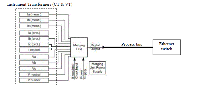
the primary equipment and the process bus LAN. The merging unit concept is illustrated in figure 3. |
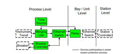
| The implementation of the merging unit concept in substation automation system can be better understood with the
simplified block diagram of a substation using the proposed system as illustrated in figure 4 [8]. |
PROPOSED AUTOMATION SYSTEM MODEL |
| The block diagram of the proposed automation system model is presented in figure 5. It is a modular system in which
the merging units are seen as modular objects making up the system. Thus with respect to the 33kV side of a typical
injection substation, there are five merging units in the model each of them representing a data merging module for
each bay of the substation namely bay 1 to bay five. Note that bay 4 represents the center bay also referred to as the bus
coupler. |
| The modular substation automation model is an IEC61850 based system for the monitoring and control of a substation.
Each bay in the substation as shown in Figure 5 is attended by a merging unit which can be linked to other devices such
as the Human-Machine-Interface (HMI), station controllers, differential protections, and other bays within the
substation through the IEC61850 Ethernet connection. This model focuses on the function of the merging unit as the
basic substation automation component for bay monitoring and control. In this model, a merging unit serves as a unit
control element with internal capabilities of real-time decision making as well as communication to other systems
components for higher or alternative decision making. Hence, an IEC61850 compliant bus provides a connection
between a merging unit and an Ethernet switch for data connection. |
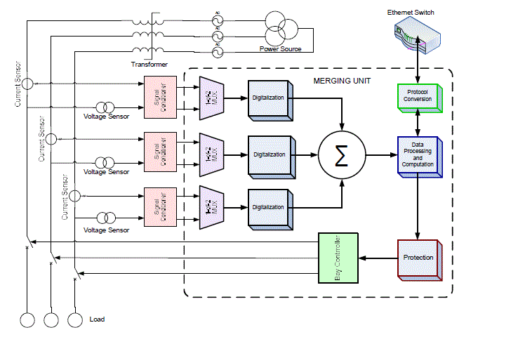
| The merging unit is made to render real-time services for the control of the bay. As shown in figure 6, the bays consist
of three phase supply lines with circuit breakers for control and protection purposes. The control parameters are the
voltage and current sensed on each line. |
| Attached to each line is a voltage sensor or transducer (VT) and a current sensor or transducer (CT) which senses the
voltage and current flowing through the line. The sensed voltage and current signals are then fed to a signal
conditioning unit where they are amplified or attenuated, filtered, etc. This conditioning process makes the signals
clean enough and in the appropriate form for the next stage to handle. |
| Further, the conditioned signals from each line are multiplexed (through a 2-line-to-1-line multiplexer) and passed into
a digitization process where they are sampled and converted to their digital form. The digitized signals are then merged
into a group data and passed into a data processing and computational unit for decision making. |
| Therefore, the basic functions required to be performed by each merging unit are summarized as follows:
- signal multiplexing, analog to digital conversion, data merging, data processing, data acquisition, protocol
conversion, communication, overcurrent protection and, bay control |
A Development of Mathematical Model for the System |
| In this subsection, we present the step by step analysis of how the mathematical model of the system was derived. The
goal here is to determine the mathematical relationships between the parameters that can enable us achieve effective
and reliable monitoring and control of the substation system using the proposed merging unit model. These parameters
are simply currents and voltages sensed by the current and voltage sensors used in the substation whose values can be
used to determine what control or protection action to be taken at any particular time. |
Signal Flow Analysis |
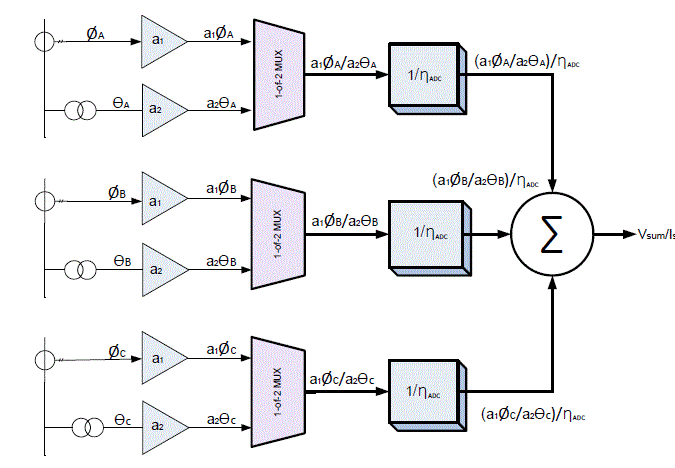
| Figure 7 shows the signal flow from the lines to the processing and computational unit within the merging unit.
Assuming Ø is the current output sensed by a current sensor and ϴ is the voltage output from a voltage sensor (VT),
then for each line (A, B and C) the output representations are: |
| Line A: voltage = ϴA and current = ØA - - - - - - - (1) |
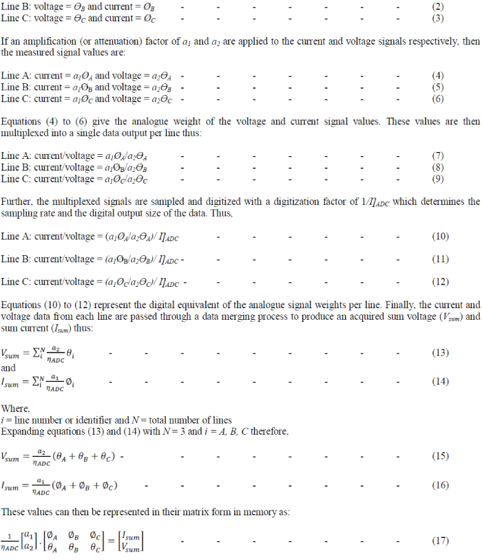 |
| Equation (17) therefore represents the complete voltage and current parametric behaviour of the bay and can be used to
effectively monitor, control and protect the substation at the bay level. |
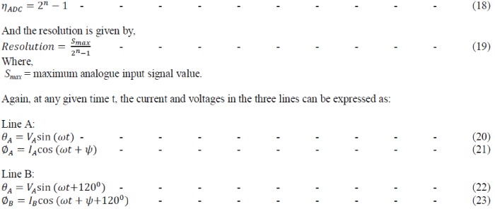
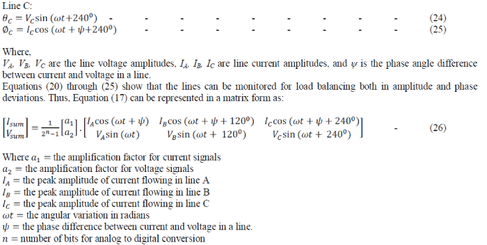
| The value ȠADC depends on a factor n = number of bits of the digitizing analogue-to-digital converter (ADC) which
defines the resolution of the output digital value with respect to the input signal range. In order words, the resolution
defines how well the digital value equivalent accurately represents the analogue signal values. Thus ȠADC is determined
by: |
 |
 |
B Block diagram overview of the Merging Unit Design |
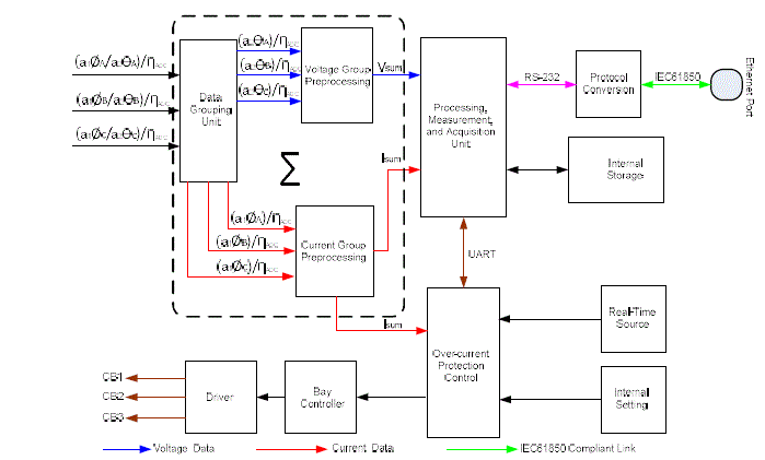
| Figure 8 shows a detailed merging process and data flow around a merging unit. First, the digitized values are passed
into a data grouping unit where they are separated into current and voltage groups. |
| The current and voltage data groups are pre-processed separately and passed to the processing, measurement and
acquisition unit where the data are processed, measured and stored. The current data group is also directly fed to an
over-current protection unit for real-time critical response as determined by preset internal settings. The over-current
protection unit can equally send and receive control information to and from the measurement and processing unit for
effective bay switching through the line circuit breakers (CB1, CB2, and CB3). |
| Finally, the merging unit communicates with the rest systems components through its IEC61850 compliant bus made
possible by passing the data via a protocol converter. The conversion is necessary since most devices use other
terminal technologies such as Recommended Standard (RS-232) serial bus, Serial Peripheral Interface (SPI), Inter-
Integrated Circuit (I2C), etc at their outputs. |
CONCLUSION |
| In this work, an overview of conventional methods of implementing merging unit design in substation automation
systems was presented and an improved merging unit model having a built-in protection and control function was
proposed. A mathematical model was developed for the proposed merging unit model for possible software simulation. |
FUTURE WORK |
| Having theoretically developed the merging unit model, we sought for relevant simulation tools that can enable us
implement the model and generate tangible and authentic results in order to validate our achievement in this work. The
various software tools which we attempted to use include MATLAB and Simulink [9], ETAP 12.0.0 Demo (Students
Edition), Proteus [10] etc. The major challenge we had was that none of the simulation softwares available to us could
completely simulate the entire system. Thus a more robust software solution must be sought and deployed in order to
simulate the entire system. Another suggestion will be to consider interfacing two or more simulation software
packages and deal with the synchronization issues that may arise. However, we are currently working on a practical
demonstration model as an improvised system which can be used to implement our design and generate the necessary
data for evaluating our proposed substation automation system. |
| |
Figures at a glance |
 |
 |
 |
 |
| Figure 1 |
Figure 2 |
Figure 3 |
Figure 4 |
 |
 |
 |
 |
| Figure 6 |
Figure 7 |
Figure 8 |
Figure 9 |
|
| |
References |
- Naidu H. K., Thanushkodi K., âÃâ¬ÃÅThe Era of Global Standard for SCADA Substation AutomationâÃâ¬ÃÂ, International Journal of Electronic Engineering Research, Vol. 1, No.3, pp. 245-257, 2009.
- Iloh J.P. and Okeke S.S.N., âÃâ¬ÃÅCommunication Technologies Evolutionary Trends in Substation AutomationâÃâ¬Ã Proceedings of the International Conference on Power Engineering - 13 (ICOPE-13), No. 171, 2013.
- Gungor V.C., Lambert F.C., âÃâ¬ÃÅA Survey on Communication Networks for Electric System AutomationâÃâ¬ÃÂ,
- www.ece.gatech.edu/research/labs/bwn/papers/2006
- Brunner C., âÃâ¬ÃÅIEC 61850 Process Bus Challenges and BenefitsâÃâ¬Ã ebookbrowse.com/iec-61850, 2011.
- Baigent D., Adamiak M. and Mackiewicz R., âÃâ¬ÃÅIEC 61850 Communication Networks and Systems in Substations: An Overview for UsersâÃâ¬Ã SIPSEP 2004 Monterrey, Nuevo LeÃÆón. www.sisconet.com, 2004.
- Liu J., Li K. and Yang H., âÃâ¬ÃÅThe Design of a Merging Unit of Electronic Transformer Based on ArmâÃâ¬ÃÂ, In Universities Power Engineering Conference, 2007 (UPEC 2007), 42nd International, pp.712-716, 2007.
- Anderson L., Brunner C. and Engler F., âÃâ¬ÃÅSubstation Automation Based on IEC 61850 with New Process-close Technologies,âÃâ¬Ã In Power Tech Conference Proceedings, 2003 IEEE Bologna, vol. 2, pp. 6., 2003.
- Skendzic V. and Hughes B., âÃâ¬ÃÅUsing Rogowski Coils inside Protective RelaysâÃâ¬Ã 2013 66th Annual Conference for Protective Relay Engineers, IEEE Xplore, vol.1, pp.1-10, 2013.
- MathworksInc, âÃâ¬ÃÅMATLAB Version 7.12.0.635 (2011a),âÃâ¬Ã The Mathworks Incorporated, www.mathworks.com, 2011.
- Lancenter Electronics, âÃâ¬ÃÅProteus Design Suite 7.6 (ISIS Professional v 7.6),âÃâ¬Ã www.labcenter.com, 2009.
|