Three phase induction motor produces severe starting torque pulsations. This causes shocks to the driven equipment and damage to the mechanical system components. In this method a novel method for starting of induction motor is proposed. The scheme depends on initial switching instances at which each phases of motor terminals are connected to the supply. A mathematical model for a three phase induction motor is developed in matlab/simulink and observed the effectiveness of the system in the elimination of torque pulsations. Hardware is implemented with an AC voltage controller using skt 24/12e thyristors. The gate control is provided with 89C51 microcontroller and the simulation results are verified through the hardware.
Keywords |
| Induction motor, motor starter, torque pulsations, modelling |
NOMENCLATURE |
| J Moment of inertia in Kg-m2 |
| ids, iqs 2-phase stator currents in Ampere |
| idr, iqr Transformed two phase rotor currents in Ampere |
| rs, Ls 2-phase stator resistance in ohms and inductance in |
| Henry |
| rr, Lr 2-phase stator resistance in ohms and inductance in |
| Henry referred to stator in ohms |
| Te Electromagnetic Torque in N-m |
| TL Load Torque in N-m |
| Vds, Vqs 2-phasee stator voltage in Volts |
| Lm mutual inductance in Henry |
| wr rotor speed in rad/sec |
| Po Number of poles |
INTRODUCTION |
| Induction motors have wide range of applications in many industrial as well as manufacturing processes. They are
highly efficient motors when operated near to its rated torque and speed. Three phase induction motor produces severe
starting torque pulsations [1] due to the interaction between slip frequency current and transient asymmetrical flux.
These torque pulsations cause shocks to the driven equipment and damage to the mechanical system components such
as gear, shafts, couplings etc. Also high inrush current is drawn by the motor which may reduce the efficiency and
cause insulation failure. A perfect starter can avoid these problems and provide smooth running for the machine. The starting methods of three phase induction motors are generally classified into four[2][3][4]: Direct online starting
(DOL), electromechanical reduced voltage starting, solid state reduced voltage starting and variable frequency drives
(VFD). Among these DOL starting is the cheapest way but it may present difficulties for the motor itself and the loads
supplied from the common coupling point due to the voltage dip in the power supply during starting. Electromechanical
reduced voltage starters consist of star delta starting, rotor resistance starting, autotransformer starting etc. But all these
conventional methods have their own draw backs such as non simultaneous switching of all the three phases to the
supply, need for frequent inspection and maintenance, failure in the moving parts due to large number of switching etc.
Soft starters or solid state reduced voltage starters are simple, reliable and economically viable and are increasingly
used in industries. Variable frequency drives are more expensive due to its converter and inverter sections. |
| The mechanical subsystem determines the amount of torque pulsations in shaft at the starting instant. In this paper a
new control strategy is proposed for eliminating the torque pulsations and provides a smooth acceleration for the motor.
The method is based on the initial switching instants of each motor terminal given to the supply. A mathematical model
is developed in matlab/simulink for a 415 V, 4.7 A, 1435 rpm and 50 Hz three phase induction motor. Hardware is
implemented using a three phase voltage controller with a gate control circuit and the simulation results are verified. |
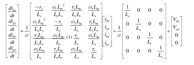
MATHEMATICAL MODEL |
| The mathematical model is developed in terms of abc axes coordinates. Reference frames are just like an observer
platforms where the unique equation of the system can be developed. The coefficients of the differential equations
depend on the rotor angle and time. The time varying inductances are eliminated by performing suitable transformation
from abc to d-q axes reference frame fixed to the stator[5][6]. The dynamic equations for the induction motor are given
below. |
 |
 |
 (2) (2) |
| and |
 (3) (3) |
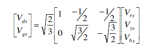
| The matrix equation (1) is derived by the proper transformations of the quantities for which the rotor reference frame
is fixed to the stator. These differential equations are used to develop a suitable system matrix for the entire model.
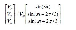
Equation (2) shows voltage equations in abc axes quantities and equation (3) shows the corresponding transformations
to d-q axes quantities. |
| The electromagnetic torque is given by |
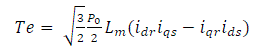 (4) (4) |
| And the speed is given by |
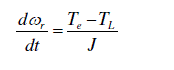 (5) (5) |
| After adding the torque balance equation for dynamic operation, the model is brought into the state space form for
simulation. Matlab function for measuring the torque, speed in radians and rpm is developed. Equation (4) and (5)
shows the torque and speed equations respectively. |
PROPOSED CONTROL SCHEME |
| In the proposed control technique the initial switching instants of motor terminals to the three phase supply is
controlled. Fig.1 shows the schematic of the starting circuit for induction motor. In this three switches are connected to
each phases of the supply. The switching instants determine the current variation and the transient torque pulsations at
the starting of induction motor. Interaction between current and flux causes the starting torque pulsations. So by
providing a gradual variation in flux the torque can be control within the acceptable limit. Initially the motor is started
with only two phases of supply. So at starting the effective flux will be varying with the rotor angle. By proper
switching of the third phase the flux jump is avoided and thus provides a smooth acceleration for the motor. |
| Extensive simulations were done with different combinations of initial switching instants. It is found that improved
torque pulsations is obtained by giving Y and B phases at starting, i.e. t = 0 and R phase with a time delay of t1 seconds. |
| This results a reduced voltage at starting hence the current is controlled. This is found to be a better technique and the
motor gets a smooth acceleration with high starting torque and minimized torque pulsations. |
SIMULATION RESULTS |
| The proposed scheme is implemented in the mathematical model developed. Three switching instances of power
supply are given below and the three input voltages are shown in Fig. 2. |
| Switching instants Y, B phases at t = 0 |
| R phase at t1 = 0.013333 sec |
| The simulation is started with a time delay of 2 sec for better understanding. So all the waveforms in the figures are
started at 2 sec. Torque profile for normal starting scheme is shown in the Fig. 3 and that for the proposed scheme is
shown in Fig. 4. It is observed that for small firing angles the starting torque pulsations are very much large while the
settling time is small. But for increased firing angles the starting torque pulsations are less but the settling time is large.
In the new scheme an improved torque profile is obtained as shown in Fig. 4. The positive as well as negative torque
pulsations are almost eliminated and a waveform without many transients is obtained. Due to reduced voltage at the
starting instant the current drowns is also much less compared to any other method. The transient time is very less and
the steady state torque is obtained within 1.5 seconds. |
EXPERIMENTAL SETUP |
| The experiment is carried out with an AC voltage controller developed with two anti parallel thyristors connected in
each phases of the power supply as shown in Fig. 5. Thyristor is of type skt 24/12e with ratings 1200 V, 50 A. The
switching instants are determined by the firing circuit. Firing circuit consists of zero crossing detectors, microcontroller
and pulse transformers. The programming is done in 89C51 microcontroller and the program is tested with softwares
like KEIL μvision 4 and proteus 7 professional. The proteus model and corresponding switching waveforms are shown
in Fig. 6 and Fig. 7. |
| According to the program the switching pulses for the R phase are generated after a delay of .013333 sec as
shown in the Fig. 7. After testing, the hardware is implemented. The zero crossings of all the three phases are
determined by the zero crossing detectors which use MCT 2E opto-coupler as shown in the Fig. 8 and are given to the
microcontroller and the output is processed to a triggering circuit where the pulse transformer generates triggering
signals (fig. 9). The triggering pulses generated for anti parallel thyristors connected in R phase is shown in Fig. 10(a).
And that for Y and B phases are shown in Fig. 10(b). |
| The gate signals with amplitude of 5V is generated. The minimum gate voltage required to trigger the skt
24/12e thyristor is only 3V. The entire gate drive circuit is shown in the Fig. 11. Induction motor is supplied through
the AC voltage controller; motor is accelerated smoothly and run satisfactarily. |
CONCLUSION |
| In this paper a new control strategy is presented to improve the electromagnetic torque pulsations at starting. The
initial switching instants of the motor terminals to the supply are controlled. Only two phases are given at the starting
instant and the third phase is given after a short time delay. Torque profile is seemed to be improved with minimized
torque pulsations. AC voltage controller is developed. Gate drive circuit using 89C51 microcontroller is tested in
Proteus 7 professional. Required switching sequence is obtained. This method efficiently minimized torque pulsations
at starting, hence avoid shocks to the driven equipment and reduce damage in mechanical system components such as
gears, couplings and shafts. So this technique can be implement in industries for large induction motors. |
| |
Figures at a glance |
 |
 |
 |
 |
| Figure 1 |
Figure 2 |
Figure 3 |
Figure 4 |
 |
 |
 |
 |
| Figure 5 |
Figure 6 |
Figure 7 |
Figure 8 |
 |
 |
 |
| Figure 9 |
Figure 10 |
Figure 11 |
|
| |
References |
- W.S.Wood, F. Flynn, A. Shanmugasundaram.”Transient Torques in Induction motors due to Switching of the supply,’’ Proc. Inst. Elect.Eng., Vol.112, no.7, pp.1348-1354, July1965.
- R.M. Hamouda, A.I.Alolah, M.A.Badr, M.A. Abdel- halim , “A Comparative Study on the Starting Methods of Three phase wound-rotor Induction Motor’’,IEEE Transactions on Energy Cpnversion.Vol.14, No.4, December 1999.
- A. J. Williams and M. S. Griffith, ―”Evaluating the effects of motor starting on industrial and commercial power systems,”IEEE Trans. Ind. Applicant., vol. IA-14, pp. 292–299, July/Aug. 1978.
- J. Nevelsteen and H. Aragon, ”Starting of large motors—Methods and economics,”IEEE Trans. Ind. Applicat., vol. 25, pp. 1012–1018, Nov./Dec. 1989.
- K. Sundareswaran, Bos Mathew Jos,”Analysis , Simulation and Performance Comparison of AC Voltage Controller Fed Three wire and Four wire connected Induction Motor Drives”,IEEEIndicon 2005 Conference, Chennai, India, 11-13 December 2005.
- K Sundareswaran, Bos Mathew Jos,’’ Comprehensive Study on Starting Performance of Thyristor Controlled Induction Motor Drives’’, IEEE Indicon 2005 conference.
|