Keywords
|
| hysteresis controller, fuzzy controller, high performance controllers. |
INTRODUCTION
|
| Traditionally the loads used by consumers are linear and passive in natures which have less effect on power system but now a day most of the loads are non linear in nature. These nonlinear loads are the main cause of harmonics in power system. As a result, the voltage at different buses of power system network is getting distorted and the utilities connected to these buses are not operated as designed. The harmonic current pollute the power system causing problems such as transformer overheating, voltage quality degradation, rotary machine vibration, destruction of electric power components and malfunctioning of medical facilities etc. |
| In order to face the problem of harmonics, many solutions have been proposed. These solutions included modifications on the load itself for less harmonic emissions like the case of special structure single phase and three phase rectifier, and PWM rectifiers. Or the connection on the polluted power grids of other traditional or modern compensation systems. |
| Most of traditional harmonic reduction solutions include the use of harmonic trapping passive filters based on RLC elements. However, passive filters have the demerits of fixed compensation, large size, and resonance. During the last three decades, researchers were encouraged by the development of power electronics industry, the revolution in digital signal processing production and the increasing demand for efficient solutions of power quality problems including harmonics problem. They were encouraged to develop modern, flexible, and more efficient solutions for power quality problems. These modern solutions have been given the name of active compensators or active power filters. The objective of these active power filter abbreviated mostly APF is to compensate harmonic currents and voltages in addition to selective reactive power compensation. Although there are different types of APF, the Shunt APF is still the most famous and used type APF. The main function of Shunt Active Power Filter is to cancel harmonic currents occurring in power grids. |
| The organization of this paper is as follows. This paper initially discusses the various current control schemes for shunt active filter. The PI controller is first described followed by Hyterisis controller, dead beat controller and fuzzy controller with their limitations. Finally the limitations are overcome by high performance current controller like multiple resonant controllers, Proportional integral plus resonant controller, vector PI controller and PI plus VPI controller. |
LITERATURE REVIEW
|
| The literary of APF is very rich and covers many aspects including power topologies, control theories, and harmonic extraction and reference generation methods of APF. Since their basic compensation principles were proposed around 1970, much research has been done on active filters and their practical applications. The paper [1] has discussed the difference in the dynamic performance of the three most popular current control techniques for active filter applications. The study shows dead beat controller gives fastest performance but its performance depends upon the parameter of active power filter, the results show a certain superiority of the hysteresis control but still it have resonance problem and chances of switching frequency losses. The need for high performance controller arises from these limitations. A current control scheme for selective harmonic compensation with shunt APF has been proposed in [2,3]. The method employs an array of resonant current controllers, one for the fundamental, and one for each harmonic, implemented in fundamental reference frame. Each pair of harmonics filtered by one controller thus reduces number of controllers. The VPI control had superior behavior in terms of stability and wider BW in the experimental tests. It maintains stable operation at high frequencies due to the lack of resonant peaks in the frequency characteristic [3]. Overall stability improved by selective harmonic compensation but this method is expensive in terms of real time calculations. [4] Proposes a detailed nonlinear control technique for a three-phase SAPF. It has two inner current loops and an outer dc bus voltage regulator loop. The main problem with this method is the delay that occurs when the control system is digitally implemented. To overcome this drawback, a computational control delay compensation method is proposed, which delaylessly and accurately generates the SAPF reference currents. In [5] author demonstrates the feasibility of four-switch three-phase inverters. The common mode voltage generated by the four-switch three-phase converter is evaluated and compared to that provided by the standard six-switch three-phase inverter. It has been found that the reduced switch topology of the AF systems operates well with the control algorithms [6]. Through extensive experimentation, it has been found that it is possible to eliminate two voltage sensors which may be needed for reliable operation with other control techniques. It reduces cost and complexity of real time system and it also raises the reliability and works well in presence of distortion in the voltage at PCC. |
CURRENT CONTROLLER
|
| A. PI controllers – |
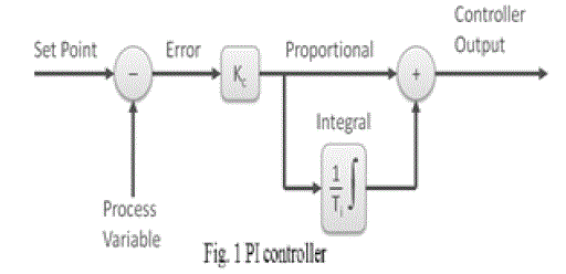
| Fig 1 shows the block diagram of the proposed PI control scheme for the active power filter. The DC side capacitor voltage (Vdc) is sensed and compared with a reference voltage (Vdc,ref). This error e =Vdc,ref −Vdc at the nth sampling instant is used as input for PI controller. The error signal is passed through Butterworth design based Low Pass Filter (LPF). The LPF filter has cutoff frequency at 50 Hz that can suppress the higher order components and allows only fundamental components. The PI controller is estimate the magnitude of peak reference current Imax and control the dc-side capacitor voltage of voltage source inverter. Its transfer function is represented as in (1): |
 |
| Where, [KP =0.7] is the proportional constant that determines the dynamic response of the Dc side voltage control and [KI =23] is the integration constant that determines it’s settling time. The proportional integral controller is eliminating steady state error in the DC-side voltage. |
| The conventional version of the linear current controller performs a sine-triangle PWM voltage modulation of the power converter using as the modulating signal the current error filtered by a proportional integral (PI) regulator. It is worth noting that we have here considered the original analog implementation of the PWM technique, since it ensures to the system the fastest possible speed of response. A sudden change in the modulating signal is indeed instantaneously turned into a duty-cycle variation, without the unavoidable delay equal to one-half of the modulation period, in the case of space-vector modulation (SVM), or to a whole modulation period, in the case of sampled PWM. |
| The application of these modulation techniques can only reduce the system’s speed of response. Nevertheless, the linear current control technique with analog PWM, although very simply implementable by means of analog circuitry, provides a rather unsatisfactory performance level as far as active filter applications are concerned. This is mainly due to the limitation of the achievable regulator bandwidth which, as it is well known, is implied by the necessity of sufficiently filtering the ripple in the modulating signal. This necessity compels one to keep the loop gain crossover frequency well below the modulation frequency. This reflects in a poor rejection of the disturbances injected into the current control loop, mainly due to the ac line voltage at the fundamental frequency. To overcome this limitation, recent versions of the linear current control exploit the rotating frame. It is noticeable that, for this kind of application, to perform the – transformation, there is no need to know the instantaneous phase angle of the sinusoidal waveforms. The main advantage of such a solution is that the fundamental harmonic components of voltage and current signals appear constant to the current regulator. Therefore, the line voltage, which is almost sinusoidal, is seen by the current regulator as a constant quantity. As a consequence, the rejection of this disturbance is much more effective. On the other hand, the bandwidth limitation of the PI regulators, which remains unchanged, still implies significant errors in the tracking of the high-order harmonic components of the current reference. In active filter applications, these errors usually reflect in a not completely satisfactory quality of harmonic compensation. [8]. |
| B. Hysteresis current control - |
| Hysteresis current control is a nonlinear closed-loop current control method and currently the most widely used in the APF control, which forms a dead zone of a given current by hysteresis comparator. The basic idea of hysteresis current control is to keep the current inside the hysteresis band by changing the switching state of the converter each time the current reaches the boundary. A hysteresis current controller is used to generate switching pluse required for VSI. In the hysteresis controller the reference compensation current is compared with the actual current that is being injected by the compensation circuit. A positive pulse is produced if the actual current tends to decrease below the lower hysteresis limit, while the negative pulse is produced if the current exceeds the upper hysteresis limit. Thus in a hysteresis current controller the actual compensation current is forced to stay within a particular hysteresis band. [9] |
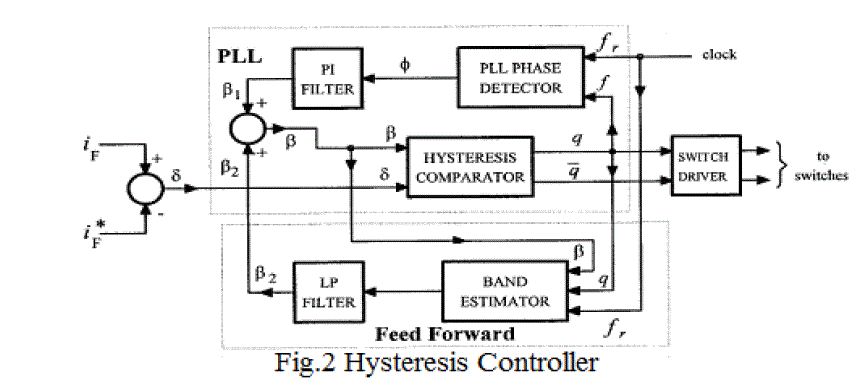
| The switching action of the PWM converter is controlled through hysteresis error of the feedback current and command current. This method has the characters of simple circuit, small switching loss, fast dynamic response, but the switching frequency of the system response speed and current tracking accuracy is affected by the hysteresis broadband. In addition, independent control of three phases result in phase interference in none neutral line three-phase inverter. The basic implementation of the hysteresis current controller derives the switching signals from the comparison of the current error with a fixed hysteresis band. Although simple and extremely robust, this control technique exhibits several unsatisfactory features. The main one is that it produces a varying modulation frequency for the power converter. This is, in general, responsible for various problems, from the difficulty in designing the input filters to the generation of unwanted resonances on the utility grid. Another negative aspect of the basic hysteresis control is that its performance is negatively affected by the phase currents’ interaction, which is typical of three-phase systems with insulated neutral. Fig. 2 shows the simplified scheme of the implementation of such a controller. |
| Many improvements to the original control structure have been suggested by industrial applications. First of all, phase current decoupling techniques have been devised. Secondly, fixed modulation frequency has been achieved by a variable width of the hysteresis band as function of the instantaneous output voltage. This is achieved either by means of a phaselocked loop (PLL) control or by a feed forward action operating on the control thresholds. |
| As can be seen, the controller modifies the hysteresis band by summing two different signals. The first is the filtered output of a PLL phase comparator and the second is the filtered output of a band estimation circuit The band estimator implements a feed forward action that helps the PLL-based circuit to keep the switching frequency constant; in this way, the output of the PLL circuit only provides the small amount of the modulation of the hysteresis band which is needed to guarantee the phase lock of the switching pulses with respect to an external clock signal. This also ensures the control of the mutual phase of the modulation pulses. All of these provisions have allowed a substantial improvement in the performance of the hysteresis current controller, as is discussed in [8]. It is worth adding that, in different applications, such as drives or PWM rectifiers, such control complexity may not be actually necessary, since the required dynamic performance is normally lower, and conventional, non hysteretic, techniques can be completely satisfactory |
| C. Dead-Beat Control (DBC) – |
| the load current and compensation current in the previous sampling period. The advantages are fast dynamic response, and easy software implementation, the disadvantages are the amount of calculation and dependence on the system parameters. In addition to the introduction of a variety of current tracking control strategy, there are many modern control methods, such as Sliding Mode Control (SMC), Space Vector Control (SVC), etc. Application of active power filter control algorithm should be based on the harmonic situation, considering the control accuracy, response speed, and the system immunity factors. |
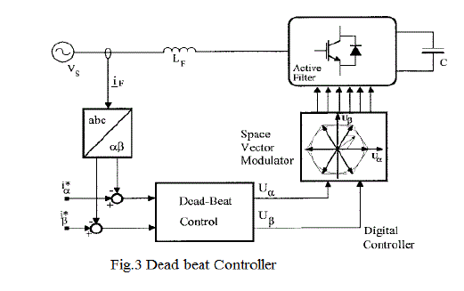
| In the conventional implementation, the digital control calculates the phase voltage, so as to make the phase current reach its reference by the end of the following modulation period [10]–[13]. The calculations are often performed in the frame, and the space-vector modulation (SVM) strategy, which very well suits the digital implementation, is applied to the switching converter. This is essentially the situation depicted in Fig. 3. |
| An important advantage of this technique is that it may not require the line voltage measurement in order to generate the current reference. Indeed, the deadbeat control’s algorithm implies an estimation of the line voltage instantaneous value, which can, therefore, also be used for the current reference generation. |
| On the other hand, the inherent delay due to the calculations is indeed a serious drawback for this technique [13]. Due to the high required speed of response, it becomes the main limitation in active filter applications and may imply an unsatisfactory performance level. In the more recent versions [14] of the deadbeat controller, this delay is reduced by sampling the control variables and executing the control routines twice in a modulation period. The turn-on and turnoff times of the power converter switches are, therefore, decided separately in two successive control periods. As a consequence, the aforementioned delay in current reference tracking can be reduced to a single modulation period. This can be further compensated by adopting a prediction technique for the current reference [14]. Accordingly, the control algorithm interpolates the reference value for the current modulation period from those calculated in the preceding ones. Thus, by anticipating the current reference, the steady state tracking error can be virtually eliminated. On the other hand, the implied derivative action causes increased errors and overshoots in the presence of sudden reference changes. In practice, however, it turns out that, on the whole, the reference prediction technique provides a performance improvement. |
| Another key issue in this kind of control technique is the effect of the input filters commonly used to eliminate residual high-frequency harmonic components in the line currents, which are due to the inverter’s modulation. These filters are not normally accounted for in the control algorithm and therefore, undermine the stability of the current loop. To guarantee the control’s stability, certain over sizing of the system’s reactive components may be necessary. |
| D. Fuzzy Logic Controller – |
| Fuzzy logic control is deduced from fuzzy set theory in 1965; where transition is between membership and non membership function. Therefore, limitation or boundaries of fuzzy sets can be undefined and ambiguous; FLC’s are an excellent choice when precise mathematical formula calculations are impossible. |
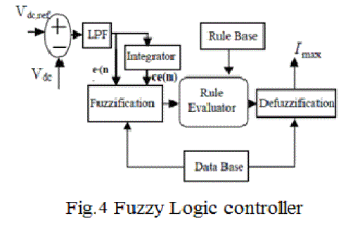
| Fig 4 shows block diagram of the fuzzy logic control scheme. In order to implement the control algorithm of a shunt active power filter in a closed loop, the dc capacitor voltage VDC is sensed and then compared with the desired reference value VDC,ref. The error signal e =VDC,ref −VDC is passed through Butterworth design based LPF with a cut off frequency of 50 Hz; that pass only the fundamental component. The error signal e(n) and integration of error signal is termed as ce(n) are used as inputs for fuzzy processing. The output of the fuzzy logic controller limits the magnitude of peak reference current Imax . This current takes care of the active power demand of the non-linear load and losses in the distribution system. The switching signals for the PWM inverter are generated by comparing the actual source currents (isa ,isb ,isc) with the reference current (isa*,isb*,isc *) using the HCC method.The main advantages of fuzzy control are its linguistic description, independence of mathematical model, robustness, and its universal approximation. A fuzzy logic controller is consisting of four stages: fuzzification, knowledge base, inference mechanism and defuzzification. The knowledge base is composed of a data base and rule base and is designed to obtain good dynamic response under uncertainty in process parameters and external disturbances.The data base consisting of input and output membership functions, provides information for the appropriate fuzzificztion operations, the inference mechanism and defuzzification. The inference mechanism uses a collection of linguistic rules to convert the input conditions into a fuzzified output. Finally, defuzzification is used to convert the fuzzy outputs into control signals. In designing of a fuzzy control system, the formulation of its rule set plays a key role in improvement of the system performance. [15] |
HIGH PERFORMANCE CURRENT CONTROLLER
|
| A. Resonant controllers – |
| In order to effectively regulate the supply currents to be sinusoidal, the current controller must have high gains at harmonic frequencies, which can be achieved by means of multiple resonant controllers tuned at harmonic frequencies. The transfer function of resonant controller is given as (2): |
 |
| The main disadvantage is that each resonant controller has a responsibility to regulate only one harmonic component. Thus, the controller complexity and computational burden are significantly increased if large numbers of harmonic currents are required to be compensated. |
| B. PI plus Resonant controller- |
| The disadvantage of resonant controller can be overcome by using PI controller with the conventional resonant controller. The aim of the PI controller is to regulate the fundamental current whereas resonant controllers are used to control the harmonic currents. However, the delay time caused by the effect of the APF and digital implementation must be taken into account if the high-order harmonics are compensated. The transfer function of this controller is given in (3). But only considering the delay time caused by digital implementation and neglect the effect of the APF: the stability margins are reduced, and undesired peaks appear in the closed-loop frequency response when the order of the compensated harmonic increases. In addition, a PI controller is utilized to compensate a small voltage drop resulting from the system impedance and the series transformer. It is also used to improve the dynamic response of the series APF. Consequently, the voltage control scheme for the series APF consists of a PI controller and a resonant controller, and the combined transfer function is given as follows: [16] |
 |
| C. Vector PI controller- |
| In order to overcome these problems, an alternative solution of the resonant controller, the VPI controller, has been introduced [7]. The transfer function of the VPI controllers (4) in the s-domain is |
 |
| The VPI controller is able to cancel the coupling term with the form1/(sLF + RF ) by selecting the resonant gain as Krh = KphRF /LF , where LF and RF are the inductance and the equivalent resistance of the LF inductor, respectively. Owing to this advantage, the VPI controller is able to remove anomalous peaks appearing in the closed-loop response without demand of delay compensation.[7] |
| D. PI plus VPI controller- |
| Adopting the superiority of the VPI controllers over resonant controllers, the resonant controllers given in GPI-R are used to replaced by controller GVPI, [7] the transfer function of the proposed PI-VPI current controller (5)in the s-domain is given as follows: |
 |
SUPERIORITY OF PI PLUS VPI CONTROLLER
|
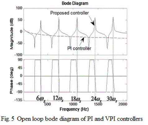
| In order to investigate the superior characteristics of the proposed PI-VPI controller over the traditional PI controller, Fig. 5 describes open-loop Bode diagram for the traditional PI and the vector PI controllers for the case of h = 6n, n = 1. . . 5, ωs = 2π60 rad/s, Kph = 1, and Krh = KphRF /LF. As illustrated in Fig. 5, at low frequency (less than 20 Hz), the gains of both the PI and proposed controllers are high and comparable, but at high frequencies, i.e., selected resonant frequencies (6ωs, 12ωs, 18ωs, 24ωs, and 30ωs), the gain of the PI controller is significantly reduced while the proposed controller produces very high gains for ensuring zero steady-state errors in compensating the harmonic currents. |
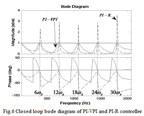
| As shown in Fig. 6, the VPI controller provides unity gain and zero phase-shift for all selected resonant frequencies while there are undesired peaks in the closed loop of the PI-R controller. Thus, the use of VPI controllers significantly improves the stability margin and accuracy of the proposed current controller. |
CONCLUSION
|
| This paper has discussed the different current control technique used for harmonic compensation in three phase shunt active power filter. The PI controller, Hyteresis controller, dead beat controller and fuzzy controller have been explained with their advantages and disadvantages. The Superiority of VPI high performance current controller is also explained with various bode diagram. |
Figures at a glance
|
 |
 |
 |
| Figure 1 |
Figure 2 |
Figure 3 |
 |
 |
 |
| Figure 4 |
Figure 5 |
Figure 6 |
|
| |
References
|
- S. Buso, L. Malesani, and P. Mattavelli, “Comparison of current control techniques for active filters applications,” IEEE Trans. Ind. Electron, vol. 45, no. 5, pp. 722–729, Oct. 1998.
- C. Lascu, L. Asiminoaei, I. Boldea, and F. Blaabjerg, “High performance current controller for selective harmonic compensation in active power filters,” IEEE Trans. Power Electron, vol. 22, no. 5, pp. 1826–1835, Sep. 2007
- C. Lascu, L. Asiminoaei, I. Boldea, and F. Blaabjerg, “Frequency response analysis of current controllers for selective harmonic compensation in active power filters,” IEEE Trans. Ind. Electron,, vol. 56, no. 2, pp. 337–347, Feb. 2009.
- S. Rahmani, N. Mendalek, and K. Al-Haddad, “Experimental design of a nonlinear control technique for three-phase shunt active power filter,” IEEE Trans. Ind. Electron, vol. 57, no. 10, pp. 3364–3375, Oct. 2010.
- M. B. de R. Corrêa, C. B. Jacobina, E. R. C. da Silva, and A. M. N. Lima, “A general PWM strategy for four-switch three phase inverter,” IEEE Trans. Ind. Electron., vol. 21, no. 6, pp. 1618–1627, Nov. 2006.
- B. N. Singh, B. Singh, A. Chandra, P. Rastgoufard, and K. Al-Haddad,“An improved control algorithm for active filters,” IEEE Trans. Ind. Electron, vol. 22, no. 2, pp. 1009–1020, Apr. 2007.
- Quoc-Nam Trinh and Hong-Hee Lee, “An Advanced Current Control Strategy for Three-Phase Shunt Active Power Filters” IEEE Trans. Ind Electron, vol. 60, no. 12, Dec. 2013
- Simone Buso, Luigi Malesani and Paolo Mattavelli “Comparison of Current Control Techniques for Active Filter Applications” IEEE Trans. Ind. Electron, vol. 45, no. 5, Oct 1998.
- J. B. Dixit, AmitYadav “Electrical Power Quality” Laxmi Publications, Ltd., Jan 1, 2010.
- K. P. Gokhale, A. Kawamura, and R. G. Hoft, “Dead beat microprocessor control of PWM inverter for sinusoidal output waveform synthesis,” IEEE Trans. Ind. Applicat., vol. IA-23, pp. 901–909, Sept./Oct. 1987.
- T. Kawabata, T. Miyashita, and Y. Yamamoto, “Dead beat control of three phase PWM inverter,” IEEE Trans. Power Electron., vol. 5, pp. 21– 28, Jan. 1990.
- T. Ohnuki, O. Miyashita, T. Haneyoshi, and E. Ohtsuji, “High power factor PWM rectifiers with an analog pulsewidth prediction controller,” IEEE Trans. Power Electron., vol. 11, pp. 460–465, May 1996.
- P. Tenti, A. Zuccato, L. Rossetto, and M. Bortolotto, “Optimum digital control of PWM rectifiers,” in Proc. IEEE IECON’94, 1994, pp. 382– 387.
- D. G. Holmes and D. A. Martin, “Implementation of direct digital predictive current controller for single and three phase voltage source inverters,” in Conf. Rec. IEEE-IAS Annu. Meeting, 1996, pp. 906–913.
- Uma Mahesh.J, Musthak Ahmed Shaik, “Fuzzy logic controller of a series active power filter for Power Quality improvement” International Journal of Modern Engineering Research (IJMER) Vol.2, Issue.2, Mar-Apr 2012 pp-412-415.
- Quoc-Nam Trinh and Hong-Hee Lee, “Novel Control Strategy for a UPQC under Distorted Source and Nonlinear Load Conditions” Journal of Power Electronics, Vol. 13, No. 1, January 2013.
- C. Lascu, L. Asiminoaei, I. Boldea, and F. Blaabjerg, “High performance current controller for selective harmonic compensationin active
- 18.power filters,” IEEE TRANSACTIONS ON POWER ELECTRONICS, vol. 22, no. 5, pp. 1826–1835, Sep. 2007.
|