Keywords
|
| orthogonal frequency-division multiplexing (OFDM), power-line communication (PLC), multiplayer perceptron, nonlinear equalization, Mean square error (MSE) |
INTRODUCTION
|
| The low voltage power distribute networks are used as a local loop in communications for a range of customer services in the residential and industrial area, such as several electrical utilities and manufacturers of electrical products in metering, communications and distribution automation. Due to recent demands in the area of communication networks the electrical power supply system is on the way to migrate from a pure energy distribution network to a multi-purpose medium delivering energy, voice and various data services. Especially Internet access is in the focus of the efforts of various research activities. |
| The power-line communication by OFDM can realize high-speed power-line network. Although power-line channels are bad transmission medium because of their channel transfer functions and additive noise, OFDM can efficiently adapt itself to channel characteristics and achieve good performance. It is possible for OFDM to control its sub-carrier modulation scheme, transmission power and so on because each sub-carrier in the OFDM signal is orthogonally arranged and can be controlled independently. |
| Due to the considerable differences between power distribution networks and conventional communication mediums in topologies and physical properties, the implementation of such a system is not an easy task. In the PLC system, the transmission performance is greatly degraded by different kinds of destructive interference. For example, different propagation delays of multipath, non constant amplitude and nonlinear phase response of the channel will cause inter symbol interferences (ISI). Furthermore, due to the dynamic fluctuation of power load, power-line communication will experience time-varying, frequency-selective fading in the multipath propagation. Other interferences, such as impulse noise and impedance mismatching, would also crucially degrade the signal-to-noise ratio (SNR) in the PLC system. To overcome these problems, orthogonal frequency-division multiplexing (OFDM) was proposed as a new and efficient method for high-bit-rate communications [1]. |
| Loss of the orthogonality between the sub channels is a great problem for OFDM. Although it is possible to eliminate the loss of the orthogonality between the sub channels caused by ISI in the OFDM by adding a “guard interval” with a length greater than the maximum spreading delay of the channel, loss of sub channel orthogonality due to the inter channel interference (ICI) caused by the time-variant property is unable to be compensated. Therefore, an equalizer is required to overcome this problem. However, the commonly used single-tap equalizer assumes that the channel is time constant in the period considered and is not true for the practice. It is difficult for such an equalizer to fully compensate the influence of the time-variant properties in the nonlinear channel [2]. |
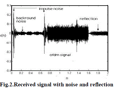
| Noise in a power line is not an additive white Gaussian noise (AWGN). The noise is categorized into four different types of noise in and extended into five types in. The five types of noise are colored background noise, narrowband noise, periodic impulsive noise asynchronous to the mains frequency, periodic impulsive noise synchronous to the mains frequency and asynchronous impulsive noise. The first three types of noise usually remain stationary and are summarized as background noise. The last two noise types are time-variant and are classified as impulsive noise. The impulsive noise has a short duration with random occurrence and a high power spectral density (PSD). It may cause bit or burst errors in data transmission. |
| Multipath effect is another serious problem for PLC because the distribution of power lines is complicated. Signal propagation usually travels along a shortest path between transmitter and receiver, but additional paths (echoes) should also be considered. This will result in a multipath scenario with frequency selective effect. |
| The rest of this paper is organized as follows. In Section II, a model of an OFDM-based PLC system is presented. Section III contains Linear Equalizer Design and section IV contains nonlinear equalizer design based on MLP. In section V, simulation and results are discussed and section VI contains conclusion. |
POWER-LINE CHANNEL CHARACTERISTICS AND OFDM SYSTEM MODELLING
|
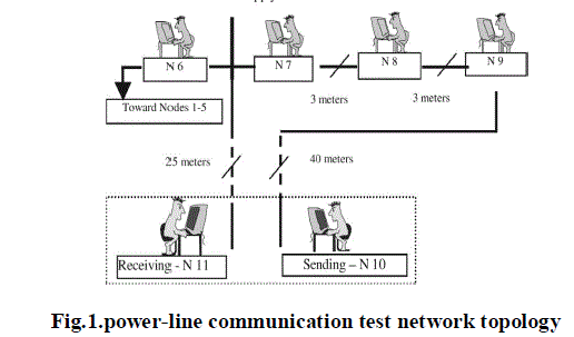
| In order to deal with the power-line channel impairments, it is necessary to investigate the characteristics of the power line as a medium for communication. Fig.1 shows the topology of the indoor power-line communication test network. The network contains a number of nodes, branches, and mismatched lines. Signal propagation through this network involves a complex phenomenon characterized by various effects, particularly impulse noise and multipath propagation[6]. The reflection existed at the joints of house service cables and house connection boxes and makes the signal transmission even more complicated [7]. As in this case, the reflection signal has the same frequency as that of the sending signal and differs in the reaching time at the receiver. A set of the practical signal received at point is shown in Fig. 2. All of the effects mentioned above can be seen from this figure. |
| The coding information of the sending signal is modulated with a D-BPSK to a series of with the amplitude of (2) |
 |
| When a signal experiences the network transmission, both the amplitude and the phase fluctuate with time, which will result in signal distortion. |
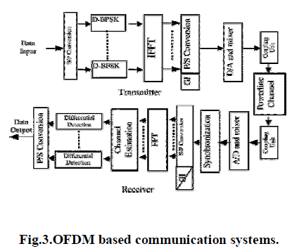
| The OFDM communication system divides a serial data stream into several parallel streams, which operate at a symbol rate lower than the original stream, and then modulates the parallel streams with orthogonal carriers. This technique divides the wideband channel into several different sub bands. The data to be transmitted are divided among several subcarriers, and the subcarrier signals are transformed into a time-domain signal by an IFFT. The output signals from the IFFT are then used to form an OFDM symbol by extending the IFFT output cyclically. For the receiver and transmitter functions, OFDM uses FFT and inverse FFT (IFFT) techniques, eliminating the necessity for a bank of mixers. A guard interval (cyclic prefix) is inserted between successive OFDM symbols in the transmission and removed prior to demodulation. Fig.3.gives an idea about power-line communication using OFDM. The received signal after FFT can be represented as (2) |
 |
| Where is the transmitting signal which is a binary sequence of . is the estimated coefficient of the channel. is the length of the window for . |
LINEAR EQUALIZER DESIGN
|
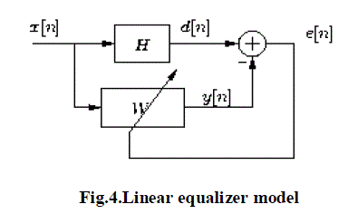
| In this paper linear equalizer is designed with LMS adaptive algorithm. The filter coefficients are updated as follows |
 |
| Where x[n] is incoming signal with interference and d[n] is the desired output and e[n] is the error signal.μ is the stability factor. |
NONLINEAR EQUALIZER DESIGN
|
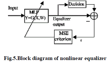
| In order to mitigate the time-varying nonlinear effects of the power-line channel, it is necessary to design a nonlinear equalizer. A self-improved nonlinear equalizer using a multilayer perceptron is proposed in this paper. This equalization gives a good compromise among the system reliability, the algorithm convergence, and the computation complexity. |
| For an equalizer based on MLP with one hidden layer of n neurons, m neurons for the input layer, and 1 neuron for the output layer, the output of the equalizer is given by(2) |
 |
| Where, |
 |
| b1 is biases for the hidden layer. |
| b2 is biases for the output layer. |
| tanh is the hyperbolic tangent function. |
| The MSE for MLP is given by (3) |
 |
| Where is the estimation of equalizer output for the sending symbol sequence, which is the output of equalizer after decision (2) |
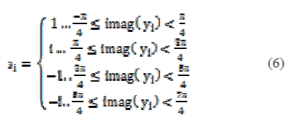 |
| The performance function of MLP is given by (2) |
 |
| The gradient of performance function is given by(2) |
 |
| Where ω denotes the parameters , of equalizer. |
| The coefficients of the equalizer can be updated as follows (5) |
 |
| Where μ is the step size of learning. |
SIMULATION AND RESULTS
|
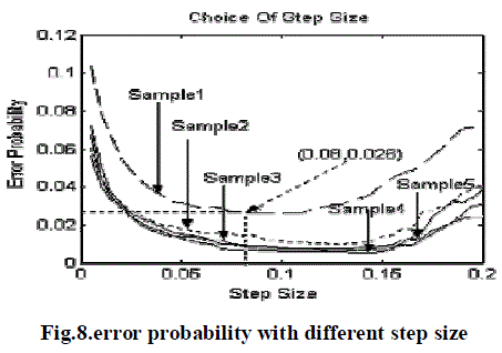
| For the simulations number of bits to be transmitted is taken as 1800. Totally 6 carriers are taken and each are assumed to carry 300 bits. The step size plays a very important role for the conver- gence, speed of the algorithm, the performance of the algorithm, as well as the robustness against channel distortion. Mathematical approaches used to determine the optimal may be very complex or even impossible for this problem. A constellation estimator is, then, used as a useful decision tool. |
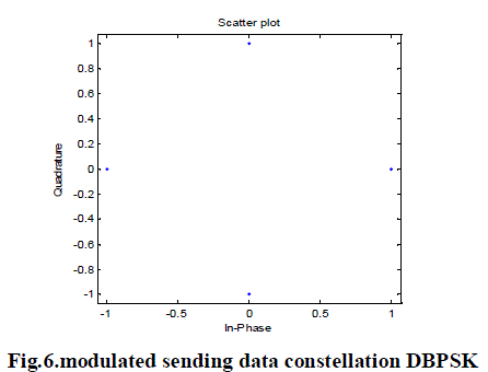
| A constellation estimator is commonly used to evaluate the distortion of the received signal. Similarly, the effect of the equalizer can be estimated by analyzing the constellation of an equalizer’s output. In this particular case, differential binary phase-shift keying (BPSK) modulation is used to assign the sending symbols to the related subcarriers so that all transmitted are situated at the following four points , where i is in a complex form as shown in fig.6. |
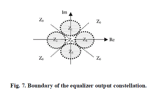
| It can be seen that the performance of the equalizer is determined by the probability of symbols distributed in the shadowed area as shown in Fig. 7, which means that the optimal step size should be able to minimize the probability at which the received signals deflect from .Instead of using BER ,Constellation error probability is used (2) |
 |
| Where is the number of samples inside the shadowed area and is the number of samples outside the shadowed area as shown in Fig.7. |
| To acquire the optimal step size, five PLC test signals are randomly selected to perform the experiment. The results are given in Fig. 8. From this figure, it is found that the step size should be chosen in the following range 0.03– 0.16. For the present application, a step size of 0.08 appears to be a good choice for both the constellation error probability minimization and the fast convergence speed. |
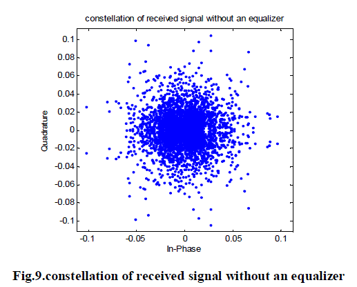
| The constellation diagram of the received OFDM signal without equalizer is given in Fig.9. It shows that received signal without an equalizer can be viewed as a sparse atom with an error probability of about 0.5019. This shows that the received signal has affected more due to the inter carrier interference. |
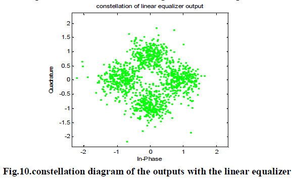
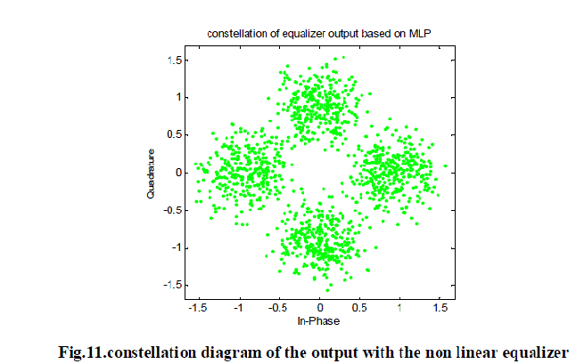
| Fig.10 shows the performance of traditionally used adaptive least mean square (LMS) linear equalizer. The error probability for the LMS equalizer is 0.0111. Fig.11 shows the performance of nonlinear equalizer. The error probability for the MLP nonlinear equalizer is 0.0028. |
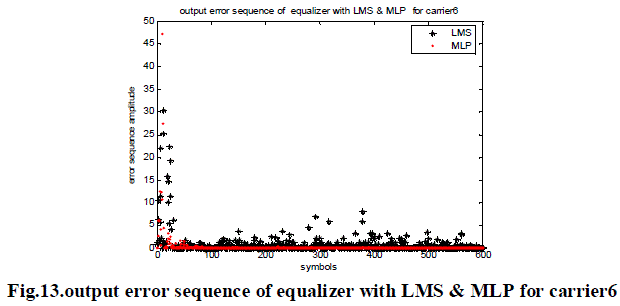
| Fig .12 to 13 shows the output error sequence of equalizer with MLP and LMS. The error in the observation window for the linear LMS equalizer is much larger than or at least equal to that of non linear equalizer. Also non linear equalizer gives a faster convergence speed when the system is subjected to the sudden changes ,which means that this kind of equalizer is able to quickly track the variations of the power-line communication systems. |
| As a new contribution in the context of power-line communication, this paper proposed a nonlinear equalization scheme to mitigate the power-line channel effects. The proposed scheme is based on the MLP. Using this scheme, a nonlinear equalizer is realized. From the results obtained by this paper we conclude that nonlinear equalizer is more effective in tracking the variation of the power-line communication channel. Now we are working on the design of non linear equalizer with self organizing maps and design of linear equalizer with adaptive algorithms like RLS, NLMS. |
Figures at a glance
|
 |
 |
 |
 |
 |
| Figure 1 |
Figure 2 |
Figure 3 |
Figure 4 |
Figure 5 |
 |
 |
 |
 |
 |
| Figure 6 |
Figure 7 |
Figure 8 |
Figure 9 |
Figure 10 |
 |
 |
 |
| Figure 11 |
Figure 12 |
Figure 13 |
|
| |
References
|
- A. R. S. Bahai and B. R. Saltzberg, Multi-Carrier Digital Communications Theory and Applications of OFDM. Norwell, MA: Kluwer, 1999.
- ChunfengLuo, Shijie Cheng, Senior Member, IEEE, LanXiong, Joseph Nguimbis, Youbing Zhang, and Jia Ma ,”A Nonlinear Equalization Method Based on Multilayer Perceptron for OFDM Power-Line Communication”, IEEE Trans. on power delivery,vol. 20, NO. 4, Oct.2005,pp.2437-2442.
- M.H.L.Chan and R.W.Donaldson, “Attenuation of communication signals on residential and commercial intrabuilding power-distribution circuits,” IEEE Trans. Electromagn. Compat., vol. EMC-26, no. 4, pp. 220–230, Nov. 1984.
- W. Y. William, Y. Zou, and Y. Y. Wu, “COFDM: An overview,” IEEE Trans. Broadcast., vol. 41, no. 1, pp. 1–8, Mar. 1995.
- J. G. Proakis, Digital Communications, 4th ed., ser. International Edition Electrical Engineering Series, McGraw- Hill, Singapore, 2001.
- X. Jiang, J. Nguimbis, S. Cheng, H. He, and X. Xu, “A novel scheme for low voltage power-line communication signal processing,” Elect. Power Energy Syst., vol. 25, pp. 269–274, 2003.
|