Keywords
|
| Three Phase Induction Motor, Solar, Boost Converter, Three Phase Inverter, Sinusoidal PWM Technique. |
INTRODUCTION
|
| Energy has become an important and one of the basic infrastructures required for the economic development of a country. Energy security is imperative for sustained growth of economy. The concern for environment, due to excessive use of fossil fuels, has led to a remarkable global effort to harness alternative energy resources. The renewable energy resources, such as, solar, wind, biomass, geothermal, etc. are environment friendly and perennial in nature [1]. Solar energy can be a major source of power. Its potential is 178 billion MW which is about 20,000 times the world’s demand. So far it could not be developed on a large scale because of large space requirement, uncertainty of availability of energy at constant rate, due to clouds, winds, haze, etc. Utilization of solar energy is of great importance to India since it lies in a temperature climate of the region of the world where sun light is abundant for a major part of the year. |
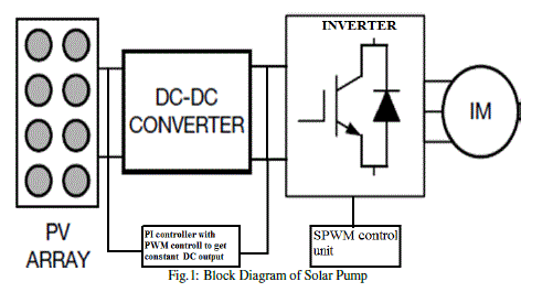
| The applications of solar energy which are enjoying most success today are solar water heating, solar cookers, food refrigeration, solar furnaces and solar photovoltaic (PV) cells. In this work, solar photovoltaic cells, which can be used for conversion of solar energy directly into electricity for water pumping in rural agricultural purposes is concentrated. The energy conversion in photovoltaic system for the application in a water pump system is shown in fig 1.It permits solar generated electrical power to be delivered to the load in our case an electric pump. It consists of solar array, DCDC converter, battery storage, inverter and load. Solar array may be tracking arrays or fixed arrays. A tracking array is defined as one which is always kept mechanically perpendicular to the sun-array line so that all times it intercepts the maximum isolation. A fixed array is usually oriented east west and tilted up at an angle approximately equal to the latitude of the site. Fixed arrays are mechanically simpler than tracking arrays. A DC – DC Converter can be considered as DC equivalent to an AC transformer with a continuously variable turns ratio. Since the output of the solar array is very less, a Boost regulator is used to increase the output voltage level. Figure 1 shows the block diagram of the solar based water pump. The Boost regulator provides an output voltage which is less than or greater than the input voltage[7]. The input current of this regulator is continuous. It has low switching losses and has high efficiency. The solar generated electric energy may be stored in the battery storage. It provides continuous power supply to the load without interruption. Inverter is a solid state circuit which converts the battery bus voltage into AC of required frequency and phase to match that needed to integrate with the utility grid or to a frequency sensitive load like AC motors[10]. The configurations of inverters are 120 degree conduction mode and 180 degree conduction mode. Among these two configurations, the inverter with 180 degree conduction mode is used to get its own technical advantages. |
DC-DC (BOOST) CONVERTER
|
| A boost converter is a specific type of dc-dc power electronic converter whose goal is to efficiently step up DC voltage to a higher level with minimal ripple. |
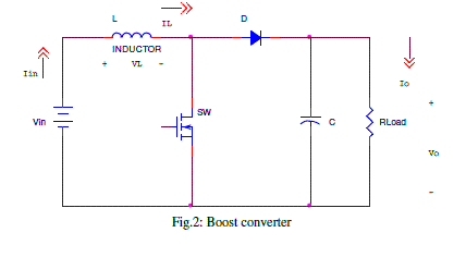
| The boost is a popular non-isolated power stage topology, sometimes called a step-up power stage. Power supply designers choose the boost power stage because the required output is always higher than the input voltage. The input current for a boost power stage is continuous, or non-pulsating, because the output diode conducts only during a portion of the switching cycle. The output capacitor supplies the entire load current for the rest of the switching cycle. Figure 2 shows a simplified schematic of the boost power stage. Inductor L and capacitor C make up the effective output filter. Resistor RLoad represents the load seen by the power supply output. |
| A. Circuit Operation: |
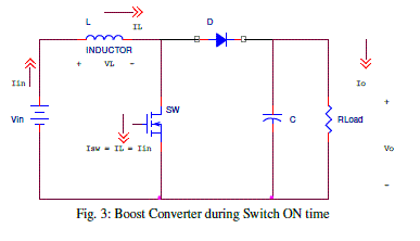
| A simplified, qualitative way to visualize the circuit operation is to consider the inductor as an energy storage element. When SW is ON, energy is added to the inductor. When SW is OFF, the inductor and the input voltage source deliver energy to the output capacitor and load. The output voltage is controlled by setting the on time of SW. For example, by increasing the on time of SW, the amount of energy delivered to the inductor is increased. More energy is then delivered to the output during the off time of SW resulting in an increase in the output voltage. When the switch is ON for a time duration DT, the switch conducts, the inductor stores energy. This results in a positive voltage across the inductor. This voltage causes a linear increase in the inductor current IL. Figure 3 shows a simplified schematic of the boost converter during ON time. |
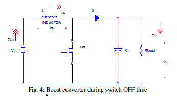
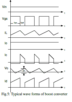
| When the switch is turned OFF, because of the inductive energy storage, the input supply voltage and the energy stored in the inductor adds and delivers to the load. This current now flows through the diode, and for time duration (1-D) T until the switch is turned on again. Figure 4 shows a simplified schematic of the boost converter during OFF time. Therefore, a converter and its control should be designed based on both modes of operation. However, for this course we only consider the dc-dc converters operated in CCM. Figure 5 shows the typical wave forms of the boost converter. |
THREE PHASE INVERTER AND CONTROL SCHEME
|
| An inverter is a circuit that converts DC sources to AC sources. Inverters are used in a wide range of applications from small switched power supplies for a computer to large electric utility applications to transport bulk power. This makes them very suitable for when you need to use AC power tools or appliances. |
| Power inverters produce one of three different types of wave output: |
| • Square Wave |
| • Modified Square Wave (Modified Sine Wave) |
| • Pure Sine Wave (True Sine Wave) |
| In photovoltaic system, the DC/AC inverter is used to converts the power of the source by switching the DC input voltage in a pre-determined sequence to generate AC voltage output. Equivalent circuit of three-phase inverter is shown below. It has six switches that turn on and off to obtain a sinusoidal output. Pulse Width Modulation is a technique that use as a way to decrease harmonic content in the inverter circuit. The supply of an induction motor by the solar generator requires the use of an inverter which transforms the DC-voltage into a three phase AC-system with variable frequency and voltage. There are two basic types of forced-commutated inverter: The current source inverter and the voltage source inverter. This chapter is focus on detailed study and modeling of three phase inverter as a frequency changer modulated by Sinusoidal Pulse Width Modulation (SPWM). |
| A. The 180 Degree Mode Voltage Source Inverter: |
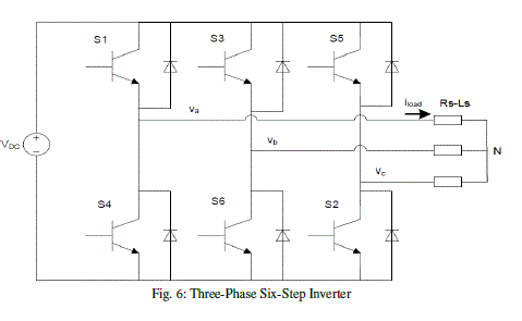
| The DC voltage obtained from the PV array is converted to AC voltage with the help of inverter. A voltage source inverter provides a firm link voltage across the motor terminals. While the load current adjust itself according to the impedance of the motor. Here six-step180 degree mode inverter is used to obtain a three-phase voltage output from DC source. The prime reason behind using a six-step inverter is only to minimize the switching losses since the phase voltage in this case is a six-step wave. Three-phase voltage source inverter is a combination of three single-phase bridge circuits. A simplified diagram of a basic three-phase inverter bridge is shown in figure 6. There are diodes in antiparallel in addition to the main power devices. These diodes are called the return current or feedback diodes. It provides an alternate path for the inductive current. |
| To obtain the three-phase AC current in six-step inverter, six gating signals need to be applied to the six switches of the inverter. The waveforms of gating signals H1, H3 and H5 are shown in figure 6. H1, H3, H5 are 3 phase symmetrical switching function with phase shift 120°. To produce the symmetrical three phase voltages across a three phase load the devices are switched ON for 180°. The switching signals of each inverter leg are displaced by 120° with respect to the adjacent legs. The switching signals S1 and S4 are complimentary, the same for S3 and S6, S5 and S2. The switching sequence will be S1S2S3, S2S3S4, S3S4S5, S4S5S6, S5S6S1, S6S1S2, S1S2S3 … for a positive sequence. The sequence will be reversed to get the negative phase sequence. The line to neutral voltages Van represented the six step of the inverter. Vbn and Vcn have the same waveform with phase shift 120°. Each switch is turned ON for 180°. The switches S1 and S4, which belong to the leftmost inverter leg, produce the output voltage for phase A. The switching signals for the switches in the middle leg, S3 and S6 for phase B, and are delayed by 120° from those for S1 and S4 respectively for a positive sequence. Similarly, for the same phase sequence, the switching signals for switches S5 and S2 are delayed from the switching signals for S3 and S6 by 120°.During step1, 0 ≤ ωt < 60, IGBT5, IGBT6 and IGBT1 are conducting, Thus, current |
 |
| It is called “six-step inverter” since there are six “steps” in the line to neutral (phase) voltage waveform as shown in figure 3.2. For a six steps inverter, the output current do not have harmonics of order three and multiples of three. |
| B. CONTROL SCHEME |
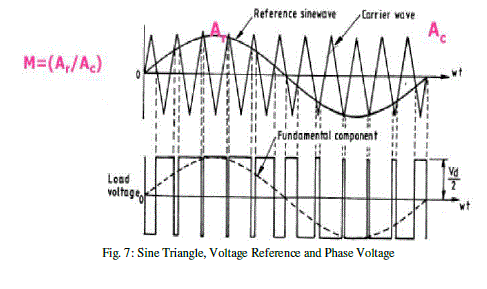
| The width of all pulses of same as in case of multiple pulse width modulation, but the width of each pulse is varied in proportion to the amplitude of a sine wave evaluated at the center of the same pulse. The distortion factor and lower order harmonics are reduced significantly. The gating signals are generated by comparing a sinusoidal reference signal with a triangular carrier wave of frequency Fc. The frequency of reference signal Fr determines the inverter output frequency and its peak amplitude Ar, controls the modulation index M, and rms output voltage Vo. The number of pulses per half cycle depends on carrier frequency. In sine-triangle three-phase PWM inverter, three sinusoidal reference voltage waveforms at each phase are compared to the same triangular carrier. The three-reference voltages are 120° apart. |
 |
 |
 |
| With this method, switch S1 is ON when triangular carrier is less than and S4 is OFF. The output voltage is equal to Vdc. The same principles apply for the other legs of the converter. To summarize the principles: |
 |
 |
 |
 |
 |
 |
 |
| In sine triangle PWM, the amplitude modulation ratio (or index) Ma is defined by |
 |
| Where Vtria: the peak amplitude of the triangular carrier, Vref: peak amplitude of the sinusoidal reference signal The frequency of the triangular waveform fpwm is the frequency of the inverter. The frequency of the reference is the fundamental output frequency. The line-to-line voltage rms value at the fundamental frequency is obtained by |
| multiplying the fundamental line to neutral fundamental frequency with √3/√2 Figure 7 shows the waveform of the sine triangle and the voltage reference comparison. |
| The switching frequency should be higher to reduce the harmonics at the output. Thus, less filter harmonics will be used. However, switching losses increase in proportion to the switching frequency. In PV system, the DC voltage that is the output from the boost converter is the input for the inverter. A controller should be implemented in order to maintain the DC voltage in a constant manner. In addition, the voltage reference determines the output frequency and amplitude desired. |
SIMULATION RESULTS
|
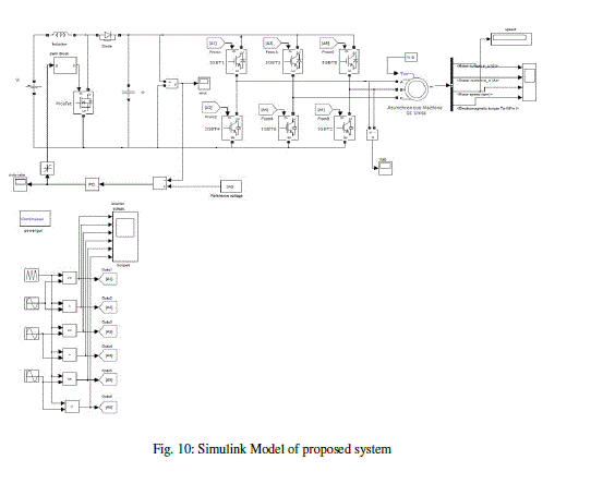
| The above shown simulink configuration consist of Boost regulator, three phase inverter and induction motor. For simplifying the power stage with minimum number of components and for achieving maximum performance, the Boost regulator is preferred over other regulators. |
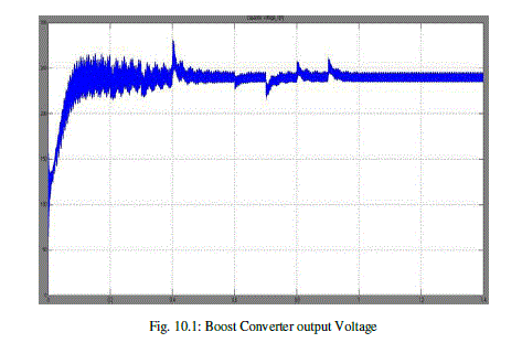
| The Boost regulator is here used in boost operation model. The dc voltage received from solar cell is boosted up to the required level and then fed into three phase inverter. The waveform in fig.9 shows the simulated output of the combination of Boost regulator, inverter and induction motor. The voltage received from solar cell is 50-150 v dc which is fed to Boost regulator. The output voltage of Boost regulator is 250v dc which will be the input to the inverter.The induction motor receives 415v ac from inverter for its operation to which the pump is connected. The first two simulation outputs show the line voltage and currents. The next two wave forms are the variation of torque and the speed with respect to time. The system reaches to the speed of 1500 rpm at 0.15 secs. |
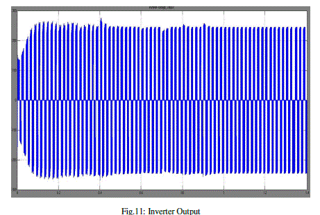
| In this simulation, the output of the boost converter is connected to the three-phase inverter. The PI controller still tracks the maximum voltage of the photovoltaic array. The carrier frequency is set at 20 kHz and reference frequency is set at 50 Hz for sinusoidal pulse width modulation technique. The three-phase inverter delivers a three-phase current to the load. Figure 11 shows a sinusoidal load current for phase a. The DC voltage produced by the photovoltaic system is converted into AC current to the load. |
| Figure 10 shows the Simulink model of the proposed converter. Inversion of boost converter output dc voltage into ac by using three phase inverter which is controlled by Sinusoidal pulse width modulation technique. The dc voltage is inverted into ac as of same magnitude with reference frequency. |
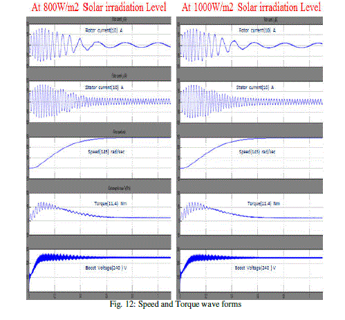
| It is clear from the below figure that speed of the induction motor is constant without any oscillation. Induction motor is controlled by v-f control technique. Speed of the induction motor is dependent on frequency of the supply voltage. Frequency of the supply voltage is maintained constant by using SPWM technique. Torque of induction motor is directly proportional to square of the supply voltage. The supply voltage is from PV source which is dependent on solar irradiation. Boost converter continuously tries to maintain constant voltage in this process some dips and spikes in the supply voltage. Due to dips and spikes there are some oscillations or fluctuations in the steady state of torque of induction motor. But oscillations in the transient state are due to parameters of stator and rotor. Due to high motor inductance, the transients lasted for longer period i.e., the machine took longer time to achieve its steady state speed, torque and current. The torque oscillations depicted in Fig 12 are based on the irradiation levels shown in Fig 12. The change in irradiation levels are in steps. However, in actual situation the change in irradiation levels happens at certain time intervals and hence the magnitude of torque oscillations is in not high as depicted in Fig 12. A higher torque oscillation if matched with the natural frequency may mechanically affect the rotor of the motor. Since the motor is only used for water pumping applications this effect is not considered as a contrast to a turbogenerator in a power plant. Due to low rotor resistance, the machine started with higher jerks, i.e., the fluctuations in |
| the transient period were more. The stator resistance must be kept as low as possible, because the steady state time increased as well as the machine started with more jerks. |
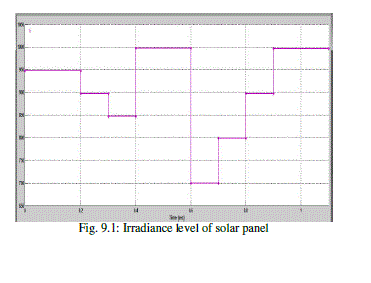
| From the above figure 12 it is observed that at two different solar irradiation levels i.e., 800W/m2 and 1000W/m2 boost converter voltage is same in both cases but PV voltage is different. But the induction motor output parameters speed, torque, stator and rotor currents are didn’t change. |
CONCLUSION
|
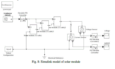
| In this paper, the study of simple photovoltaic system has been presented. From the theory of the photovoltaic, a PV array with a band of solar irradiation levels, A dc-dc boost converter which converts a variable dc voltage corresponding to the band of solar irradiation levels into a constant high dc voltage, Then the inversion of this dc voltage into three phase ac voltage using three phase inverter which is controlled by SPWM technique has been designed. Which supplies three phase induction motor and its performance has been analyzed. Finally, the system has been simulated with Simulink MATLAB. First, the simulations of the PV array showed that the simulated models were accurate to determine when the irradiance varies, the PV array output voltage & current change is shown. Then, the simulation of the dc-dc boost converter is showed that the output voltage is constant irrespective input variations are shown in figure above. The simulations of the inverter simulated models were is accurate because magnitude of ac with 50Hz frequency is same as dc and supplies the induction motor, whose performance has been analyzed by varying the stator and rotor parameters to reduce the steady state time and oscillations in the torque of motor. |
Tables at a glance
|
 |
| Table 1 |
|
| |
Figures at a glance
|
 |
 |
 |
 |
 |
| Figure 1 |
Figure 2 |
Figure 3 |
Figure 4 |
Figure 5 |
 |
 |
 |
 |
 |
| Figure 6 |
Figure 7 |
Figure 8 |
Figure 9.1 |
Figure 10 |
 |
 |
 |
| Figure 10.1 |
Figure 11 |
Figure 12 |
|
| |
References
|
- NafisaBinteYousuf, Khosru M. Salim, RafidHaider, Md. RajinAlam, Fatima Binte Zia “Development of a Three Phase Induction Motor Controller for Solar Powered Water Pump” IEEE Trans. Power Electron., vol. 24, no. 5, pp. 1198–1208, May 2009.
- Rashid, Muhammad H., Power Electronics-circuits, designs and applications. 2007.
- BenlarbiK ,Mokrani L , Nait-Said MS. A fuzzy global efficiency optimization of a photovoltaic water pumping system . Solar Energy 77(2004); 203–216 .
- Betka A, MoussiA.Performance optimization of a photovoltaic induction motor pumping system .Renewable Energy 29 (2004); 2167–2181.
- ArroufM,GhabrourS.Modelling and simulation of a pumping system fed by photovoltaic generator within the Matlab/Simulink programming environment. Desalination 209 (2007) ;23–30.
- NejibHamrouni, MoncefJraidi ,AdneneCherif .Theoretical and experimental analysis of the behaviour of a photovoltaic pumping system. Solar Energy 83 (2009) ;1335–1344.
- Bhim Singh, PuttaSwamyCL,SinghBP.Analysis and development of a low-cost permanent magnet brushless DC motor drive for PV-array fed water pumping system.Solar Energy Materials and Solar Cells .51 (1998); 55-67.
- Singh MD,KhanchandaniKB.Power Electronics.2ne edition. Tata McGraw-Hill Publishing Company Limited,2007.
- OdehI ,Yohanis YG, Norton B.Influence of pumping head, insolation and PV array size on PV water pumping system performance .Solar Energy 80 (2006) ;51–64. Betka A, AttaliA.Optimization of a photovoltaic pumping system based on the optimal control theory. Solar Energy 84 (2010); 1273–1283. Mezghanni D, Andoulsi R, Mami A, Dauphin-Tanguy G.Bond graph modelling of a photovoltaic system feeding an induction motor-pump.SimulationModelling Practice and Theory 15 (2007); 1224–1238
|