Keywords
|
| Droop control strategy, parallel operation, Voltage Source Inverters (VSIs), load current sharing. |
INTRODUCTION
|
| UNINTERRUPTIBLE power supply (UPS) systems are used to provide continuous and reliable electrical power to loads in times of unexpected power failure. By connecting the UPS inverters in parallel, its capacity is expandable. Parallel operation of inverters is gaining importance, because it increases system efficiency, provides redundancy and modularity. |
| Parallel operation of single phase or three phase inverters has lot of advantages, such as in cost, maintenance and reduction in size compared to single unit operated at low power. Inverters when connected in parallel should satisfy these basic requirements: |
| 1) proper load current sharing between the units; |
| 2) should not allow current circulation between inverters; |
| 3) each inverter should be operated independently; |
| Parallel connection of two or more inverters is practically difficult, because due to physical differences between the inverters and line impedance mismatches, the load will not be properly shared which in turn leads to circulating current among them.The control techniques reported in the literature for parallel operation of inverters are centralized control,Master-slave control [13], Circular Chain Control (3C) [5],[14], Active Load Sharing technique (ALS) [10],[12],wireless control method[16],[18]. The master-slave and central control schemes provides effective current sharing but a failure in the master or in the central unit would shut down the entire setup. The 3C and ALS scheme offers improved redundancy and modularity comparing to the previous techniques. Each inverter unit has its own parallel control system and they are connected to a common communication bus for proper sharing of data. Here a failure in the data bus would shut down the whole system. In wireless control or droop control method active and reactive power supplied to the ac bus are sensed and averaged, the resulting signals are used to adjust the voltage and frequency of the inverter reference voltage. Since this control technique does not have any control interconnection this system provides true redundancy and modularity. Each inverter operates independently and provides flexibility of connection or disconnection of an inverter at any point of connection. This control is carried out using average power values and due to the calculation of average power this method is difficult to implement. Furthermore, this method has slow dynamic response and admits larger error in distribution of power between the inverters. Hence a control strategy is used combining the principles of droop control and distributed control. Distributed control in the sense all the inverters connected in parallel has a common reference bus but they need not exchange information between them. Parallelism control employs the feedback of the inductor current of its own VSI for controlling the parallel operation |
| This Paper is organized as follows: Section II explains about the control strategy used in the project and the circuit model for the parallel connection of inverters Section II.A deals about the conventional droop control method. The central mode of control is given briefly in Section II.B. The simulation results for various loads are presented in Section III. Section IV gives the conclusion of the project work. |
CONTROL STRATEGY
|
| The structure of a single VSI module is shown in Fig.1.Each module has its own control circuit that includes two loops. The outer loop regulates the output voltage of the inverter. The inner loop is responsible for parallelism control. It uses inductor current feedback from the LC filter thus modifying the output voltage of its own inverter which is the input voltage of the LC filter. Parallelism control uses only instantaneous values to actuate the variations of each inverter thus provides fast dynamic response to current variations. This implies that all the inverters have same output voltage since they are connected to a common bus. Due to parametric and component variations between the parallel inverters each inverter shows small deviations in its output voltage . This parallelism control which is in cascade with outer loop equalizes the small variations between the inverters providing proper load current sharing among the units. |
| The model of structure showing many VSIs in parallel is shown in in Fig. 2. All the modules are connected to a common ac bus and a common voltage reference bus. The VSIs connected in parallel are identical to each other. Thus the output of the LC filter in all the units is equal. There is no connection impedance between the inverters. Each inverter works independently using only its instantaneous average values. The circuit in module1 has ac-dc converter, full bridge PWM inverter, isolation transformer and an LC filter. The voltage control loop regulates output voltage of each inverter. The current loop using inductor current feedback acts on input to LC filter. The transformer provides electrical isolation. Each inverter does not depend on the operation of other VSI hence it is easier to connect or disconnect an inverter at any point .the output response is not affected. The parallelism control plays a major role in proper current sharing between the units |
DROOP CONTROL TECHNIQUE
|
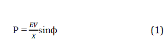
| The droop method is also called independent control. In parallel-connected UPS inverters, the active and reactive powers supplied to the ac bus are sensed and averaged, and the resulting signals are used to adjust the frequency and amplitude of the UPS inverter output voltage reference. Fig.3 presents the equivalent circuit of an inverter connected to ac bus. It shows the power flow from the impedance to the ac bus. Generally,the inverter output impedance is considered to be inductive due to the high inductive component of the line impedance and the large inductor filter. The active power and reactive power expressions are derived by considering a small phase difference ?between the inverter output voltage E and the common ac bus voltage V |
 |
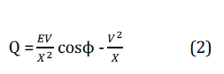 |
| Where X is the outputreactance of the inverter. |
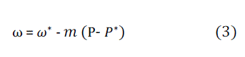
| From the above equations, P increases with the phase angle and Q with the amplitude difference (E − V). Hence, if we want a negative feedback, then we need to reduce φ and E when P and Q increase. Consequently, one solution is to introduce artificial droops into the output-voltage reference. Thus P − ω and Q − V droop schemes are often adopted. Fig.3 shows the block diagram of the conventional droop control scheme. The simplest form to implement the control law can be expressed as follows |
 |
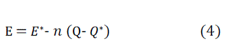 |
| Where and are the output-voltage frequency and amplitude at no load, and m and n are the droop frequency and amplitude coefficients.andare the active and reactive power references, which are commonly set to Zero. when we connect UPS units in parallel, autonomously forming an energetic island. However, if we want to share power with a constant power source, e.g., the utility grid, we should fix the active and reactive powers to be drawn from the unit. |
| The block diagram ofconventional droop control method is shown in fig.4.Here Vref is generated by adjusting the output voltage frequency and amplitude in function of the active and reactive power delivered by the inverter. Thus a small deviation in the output voltage of each inverter is balanced and consequently avoids current circulation, disequilibrium between the inverters. |
CENTRALIZED CONTROL SCHEME
|
| The block diagram of central mode of control is shown in fig.5. It consists of dividing the load current by N modules which is the current reference . The current reference value is subtracted by current of each module and the current error Δ is processed through a current control loop.The voltage control loop regulates the load voltage. This technique cannot be used in large distributed system since the load current has to be measured |
| Parallel connection of two inverters using central mode of control is shown in Fig.5. Module1, 2 are identical. The centralized controller generates the reference current. The dc inputs given to the inverters are 40v and 60v respectively. The cut-off frequency is 45Hz. The Load R = 10Ω. Ref voltage Vref = 20v. The voltage controller has Kp = 4.5 andKi = 2.The current error signal is processed through a PI controller with Kp = 0.169, Ki = 0.01. The output result for two inverters in parallel with central mode shown in fig.11. It shows load sharing between two parallel connected inverters. |
SIMULATION OF PARALLEL INVERTERS
|
| Parallel operation of four inverters is implemented using MATLAB/SIMULINK. Four 5VA inverters are connected acrossthe same load,R=10Ω.The output with resistive load is shown in fig.6.The voltage and current are in phase. The dc input given is 20v. The output of inverter is given to linear transformer with winding ratio 1:2. The signal is then filtered through LC filter with cut off frequency f=1 kHz.Using the instantaneous values of output voltage and output current , real power, reactive power is calculated. Now combining droop coefficients m and n with no load voltage E*, frequencyω*,Vref = 7v is generated. The reference voltage is compared with actual output voltage. The error signal is sent to PI controller with Kp = 6.1, Ki = 2. The signal is compared with repeating sequence of switching frequency f =2.5 kHz. The resulting firing pulses trigger thethyristor valves accordingly. With non-linear load the result is shown in fig.9. Fig.8 presents output voltage and current of two inverters in parallel with inductive load of 7VA.Fig.9 represents output with non-linear load. The output current is non-linear and by using instantaneous average values the load current is properly shared between the inverters even for non- linear load. |
| Fig.9 depicts the output for parallel inverters with different dc voltage source. The input voltages are 20v,18v,15v,13v respectively. The current amplitude of individual inverter is 0.176 Arms, 0.1414 Arms, 0.106 Arms, 0.091Arms respectively. Droop control allows the load current to be adequately shared between the inverters. The circulating current between the inverters is minimized and the current and voltages are stable.The output voltage and current for different input voltage with non-linear load is shown in Fig.10, it demonstrates the load current sharing between the units. |
| The current amplitudes are 0.282Arms, 0.212Arms, and 0.1414Arms for input voltages 20v, 16v, and 13v respectively. With droop control strategy the load current is shared properly under non-linear load. |
COMPARISON OF DROOP CONTROL AND CENTRALIZED CONTROL
|
| Load current sharing using central mode of control in fig.11. The total load current has to be calculated and hence cannot be used in large distributed systems. But the droop control method offers plug and play operation of inverters. |
CONCLUSION
|
| The control strategy for parallel inverters has been studied experimentally.This work presents the parallel operation of voltage source inverters employed in ups. The control strategy used here is distributed and droop control .The results are obtained for R-load, non-linear load. The parallelism control of each inverter is responsible for proper sharing of load current among the inverters thereby avoiding the current circulation between parallel-connected inverters. |
Tables at a glance
|
 |
| Table 1 |
|
| |
Figures at a glance
|
 |
 |
 |
 |
| Figure 1 |
Figure 2 |
Figure 3 |
Figure 4 |
 |
 |
 |
 |
| Figure 5 |
Figure 6 |
Figure 7 |
Figure 8 |
 |
 |
 |
| Figure 9 |
Figure 10 |
Figure 11 |
|
| |
References
|
- T. B. Lazzarin, T. Bauer, and I. Barbi, “A control strategy for parallel operation of single phase voltage source inverters, “in Proc... Ind. Electron. Conf., 2009, vol. 1, pp. 25–30.
- J. M. Guerrero, L. GarciadeVicuna, J. Matas, M.Castilla, and J. Miret,“Output impedance design of parallel-connected UPS inverters with wireless load-sharing control,” IEEE Trans. Ind. Electron., vol. 52, no. 4, pp. 1126–1135, Aug. 2005.
- “Differential-evolution-based optimization of the dynamic response for parallel operation of inverters with no controller interconnection,” ieee trans. ind. electron. vol. 59, no. 7, pp. 2859–2866, jul. 2012.
- Y.Wei, C. Min, J. Matas, J. M. Guerrero, and Q. Zhao-Ming, “Design and analysis of the droop control method for parallel inverters considering the impact of the complex impedance on the power sharing,” IEEE Trans. Ind. Electron., vol. 58, no. 2, pp. 576–588, Feb. 2011
- S. Xiao, L. Yim-Shu, and X. Dehong, “Modeling, analysis, and implementation of parallel multi-inverter systems with instantaneous average current- sharing scheme,” IEEE Trans. Power Electron., vol. 18, no. 3, pp. 844–856, May 2003
- N. M. Abdel-Rahim and J. E. Quaicoe, “Analysis and design of a multiple feedback loop control strategy for single-phase voltage-source UPS inverters,” IEEE Trans. Power Electron., vol. 11, no. 4, pp. 532–541,Jul. 1996.
- M. J. Ryan, W. E. Brumsickle, and R. D. Lorenz, “Control topology options for single-phase UPS inverters,” IEEE Trans. Ind. Appl., vol. 33,no. 2, pp. 493–501, Mar./Apr. 1997.
- T. Kawabata and S. Higashino, “Parallel operation of voltage source inverters,” IEEE Trans. Ind. Appl., vol. 24, no. 2, pp. 281–287, Mar./Apr. 1988
- J. M. Guerrero, L. Hang, and J. Uceda, “Control of distributed uninterruptible power supply systems,” IEEE Trans. Ind. Electron., vol. 55, no. 8, pp. 2845–2859, Aug. 2008
- Tula Dhar, J. Hua, T. Unger, and K. Mauch, “Control of parallel inverters in distributed ac power systems with consideration of line impedance effect,” IEEE Trans. Ind. Appl., vol. 36, no. 1, pp. 131–138, Jan./Feb. 2000
- M. C. Chandorkar, D. M. Divan, and R. Adapa, “Control of parallel connected inverters in standalone ac supply systems,” IEEE Trans. Ind. Appl., vol. 29, no. 1, pp. 136–143, Jan./Feb. 1993
- H. Ming, H. Haibing, X. Yan, and H. Zhongy i, “Distributed control for ac motor drive inverters in parallel operation,” IEEE Trans. Ind. Electron., vol. 58, no. 12, pp. 5361–5370, Dec. 2011
- C. Jiann-Fuh and C. Ching-Lung, “Combination voltage-controlled and current-controlled PWM inverters for UPS parallel operation,” IEEE Trans. Power Electron., vol. 10, pp. 547–558, Sep. 1995
- W. Tsai-Fu, C. Yu-Kai, and H. Yong-Heh, “3C strategy for inverters in parallel operation achieving an equal current distribution,” IEEE Trans. Ind. Electron., vol. 47, no. 2, pp. 273–281, Apr. 2000
- H. Ming, H. Haibing, X. Yan, and H. Zhongyi, “Distributed control for ac motor drive inverters in parallel operation,” IEEE Trans. Ind. Electron.,vol. 58, no. 12, pp. 5361–5370, Dec. 2011.
- Y.Wei, C. Min, J. Matas, J. M. Guerrero, and Q. Zhao-Ming, “Design and analysis of the droop control method for parallel inverters considering the impact of the complex impedance on the power sharing,” IEEE Trans. Ind.Electron., vol. 58, no. 2, pp. 576–588, Feb. 2011.
- Z. Yao and M. Hao, “Theoretical and experimental investigation of networked control for parallel operation of inverters,” IEEE Trans. Ind.Electron., vol. 59, no. 4, pp. 1961–1970, Apr. 2012.
- Z. Xiaotian and J. W. Spencer, “Linear voltage-contZ. Yao a T. B. Lazzarin, G. A. T. Bauer, and I. Barbi, “A control strategy for parallel operation of single phase voltage source inverters,” in Proc. Ind. Electron. Conf., 2009, vol. 1, pp. 25–30
- U. Borup, F. Blaabjerg, and P. N. Enjeti, “Sharing of nonlinear load in parallel-connected three-phase converters,” IEEE Trans. Ind. Appl., vol. 37, no. 6, pp. 1817–1823, Nov./Dec. 2001
|