Keywords
|
| open-ended waveguide, Radiated field, infinite ground plane, Field equivalence principle. |
INTRODUCTION
|
| We know that transmission line can be used to guide the electromagnetic (EM) energy from one point to another. In the same way , the wave guide can be used to transmit the EM energy from one point to another. At microwave frequencies (between 3-300GHz) , transmission line become inefficient due to skin effect and dielectric losses, but they will operate at all the frequencies. In case of wave guide, it operates only above the certain frequency called cut off frequency and therefore acts as a high pass filter. Both magnetic and electric fields are present in the wave guide and interaction of these fields causes the energy to travel through wave guide. The rate at which the wave travel in the wave guide is constant and approximately 300,000,000 meter per second. The hallow rectangular wave guide can propagate TE and TM modes, but not TEM waves, since only one conductor is present. The figure 1 shows the rectangular wave guide. The „a? dimension determines the frequency range of the wave guide and „b? determines the power handling capacity of the wave guide. |
ANALYSIS OF FIELD IN THE NEAR FIELD
|
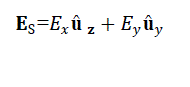
| The open ended rectangular wave guide will radiate, but not as effectively as the wave guide terminated by horn antenna. Because the wave impedance inside the wave guide does not match that of surrounding medium creating a mismatch at the open end of the wave guide. Thus a portion of the outgoing wave reflected back into the wave guide. Consider an openended rectangular wave guide which is placed in an x-y plane. If we assume that the wave guide carries only the dominant TE10 mode, the field distribution in the aperture of the wave guide is as shown in figure 1. |
| The radiation characteristic of wire antenna can be determined, once the current distribution on the wire antenna is known. For many radiator configurations such as slots, wave guide, horns etc, the current distribution is not known exactly and only experimental measurements can provide a reasonable approximation to it. |
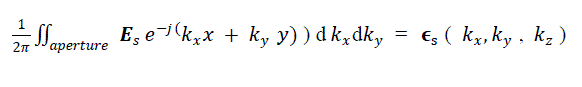
| The radiation fields for these configurations determined from the knowledge of the fields over the aperture of these devices. The aperture fields become the source of the radiated fields at larger distances. This is from the Huygens-Fresnel principle, by which actual source, such as an antenna and radiating waveguide (transmitter), is replaced by equivalent source. The fictitious source are said to be equivalent within a region because they produce the same field within that region. This is also called as field equivalence principle [2]. The open-ended waveguide terminated by an infinite ground plane as shown in figure 2. The ground plane is flat horizontal conducting surface that serves as a part of the wave guide to reflect the EM wave from the other source. |
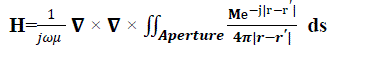
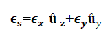
| The radiated field from the aperture of the wave guide as shown in figure 3. Let ds be the small elemental surface of the aperture. Let Es and Hs be the tangential electric field and magnetic field over the aperture respectively with surface S at z?=0 plane. These fields are assumed to be known and are produced by source fed by the wave guide. The radiated field at any point in free space can be computed with the help of field equivalence principle. In figure 3, if a tangential electric field Es is at the aperture, the equivalent magnetic current in the aperture Ms can be expressed as |
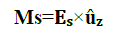 |
| Where û?? is the unit vector perpendicular to the plane containing the aperture S (in this case x-y plane). This magnetic current exists only at the aperture, since it is surrounded by an infinite ground plane, which is assumed to be perfectly conducting. |
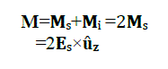
| The boundary conditions at a perfect electric conductor where the ground plane is assumed to be are vanishing tangential component of electric field E. An element of source, plus an image element of source, radiating into free space, produce zero tangential component of E over the plane bisecting the line joining the two elements [5]. While evaluating the magnetic field H, therefore, we have to consider the magnetic field due to both the magnetic current at the aperture Ms and its image Mi. The total magnetic field H is therefore, given rise to by total magnetic current M which is a sum of Ms and Mi [2]. |
 |
| The electric vector potential F at any point in space is given by |
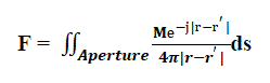 |
| Where r=xû?? +yû??+zû , r?=x?û?? +y?û?? +z?û?? and ds=dx?dy? û?? |
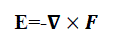
| The electric field at any point in space is given by |
 |
| The magnetic field at any point in space is given by |
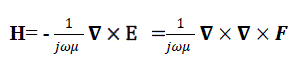 |
| Where k is free space wave number (vector wave number), it is also called as propagation factor [1], and η is the intrinsic impedance of free space defined as |
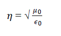 |
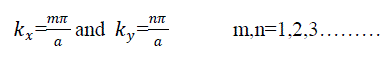
| And 0 is the permeability of free space and 0 is the permittivity of free space. Further , and satisfies the separation equation, 2 + 2 + 2 =k where , and are the separation constant. In rectangular wave guide with dimension a× b, with Eigen value or characteristic values for separation parameter and are obtained by imposing the boundary conditions[3][4]. |
 |
| Substituting the expression for F in equation 5, we obtain |
 |
| In the following Green?s identity [5] |
 |
| Therefore |
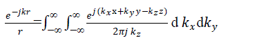 |
| Put r=|r-r?| in the above expression, then |
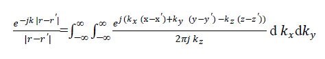 |
| In this expression x?, y? and z? refers to point on the source (aperture) and x, y and z refers to any point of observation in free space where the radiated field is to be determined. In this present problem, the source magnetic current is on z?=0 .To enforce the boundary condition at the plane of the aperture, we are interested to determine the radiated magnetic field at the z=0 plane. Substituting equation 11in equation 8 and simplifying, |
 |
| Since the Es is zero everywhere on the ground plane except at the aperture, the inner integral in 12 can be written as |
 |
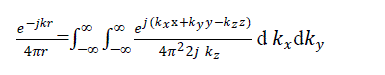
| It is apparent from the equation (13) that the inner integral of 12 is the Fourier transform of the aperture electric field. Carrying out the necessary substitution in equation 12, we get |
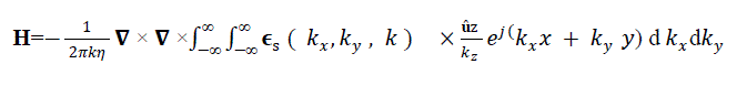 |
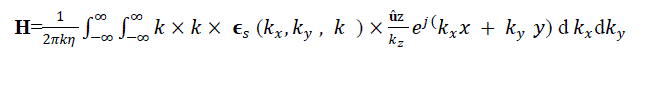
| This equation in the form of an inverse Fourier transforms. The Del operator are replaced by –jk , when taken inside the transform integral |
 |
| Since the aperture has been assumed to be tangential to the plane containing it, it can be represented as |
 |
| The transform of the field's is given by |
 |
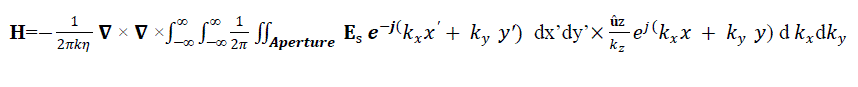
| On carrying out the cross product in equation 15 and simplifying, the components of the magnetic field at the aperture plane are given in terms of the Fourier transform of the aperture electric field as follows: |
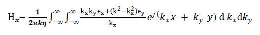 |
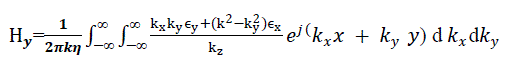 |
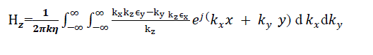 |
| For any aperture electric field distribution, therefore the magnetic field at any point in space can be found out using the approach outlined so far. |
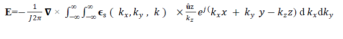
| Substituting equations 1, 2, 3, and 10 in equation 4 and sampling we get the radiated electric field from the aperture of wave guide at the near field probe. |
 |
| Or |
 |
| The del operator is replaced by –jk, when taken inside the transform integral , and sampling ,the component of electric field at any point in space are given in terms of Fourier transform of the aperture electric field as follows |
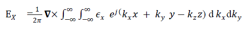 |
 |
 |
| These are the mathematical expression for magnetic field and electric field. The results are simulated using HFSS simulator. |
RESULT AND DISCUSSION
|
| The aperture in an infinite ground plane backed by a standard 2.286 x 1.016cm X - band WR-90 rectangular waveguide is used as a radiator. The dipole (probe) of resonant length at 9GHZ (0.475*λ=1.583 cm) and radius 0.005λ (0.01666cm) is used as near field measuring probe to measure the current density in the near field at different positions along the z-axis. And corresponding electric field intensity is also measured. The Ansoft?s finite elemental method based High Frequency Structure Simulator (HFSS) is used as a simulator to analyses the near field radiation from the wave guide radiator. |
| The waveguide is placed in x-y plane, the probes are positioned along the +z direction. Due to multiple reflections between the radiator and probe, the near field values are changed. The magnitude of the electric field intensity and magnitude current density in the probe at different positions is observed. The graph, variation of normalized electric field intensity and normalized current density along the ± at different positions of +z are plotted. As the probe move away from the aperture in the +z-direction, the electric field intensity is decrease slightly .But the current density is changing significantly and it is maximum when the probe is very close to the aperture of wave guide and it is decreasing if the probe move away from the aperture . For this X-band radiating waveguide, the measuring probe is placed at a distance z=0cm, z=0.25cm, z=0.5cm, z=0.75cm, z=1cm and in each case the electric field intensity and current density is measured. The results are simulated using HFSS simulator and the graphs are plotted. And graphs are plotted for normalized electric field intensity and current density for different values of z as shown in below figures. |
CONCLUSION
|
| From the above graphs if the measuring probes are placed at different positions, we are getting different result. The variation of normalized electric field intensity is more as probe is moved away from the aperture of the wave guide. But in case of normalized current density, the variation is very less and it is almost constant. This variation is due to multiple reflections and near field region is reactive. |
Figures at a glance
|
 |
 |
 |
| Figure 1 |
Figure 2 |
Figure 3 |
 |
 |
 |
| Figure 4 |
Figure 4a |
Figure 5 |
|
| |
References
|
- Balanis. C.A. Antenna Theory, 2nd edition,John Wiley & Sons, Inc., 1982.
- Paramesha and Chakarabarthy estimation of Error induced by a crossed dipole in the near field. Progress in Electromagnetic Research B, Vol.21, 27-45 2010
- David M.Pozar. Microwave engineering 2nd Edition.John Wiley & Sons, Inc., 1982.
- Samuel Y Liao, 2008 “microwave devices and circuits” , 3rd edition Pearson Prentice Hall.
- R.F. Harrington, “Time harmonics “Electromagnetic Fields “McGraw-Hill New York,1961.
|