ISSN ONLINE(2319-8753)PRINT(2347-6710)
ISSN ONLINE(2319-8753)PRINT(2347-6710)
P R Aswathy1. R. Rajesekaran2
|
| Related article at Pubmed, Scholar Google |
Visit for more related articles at International Journal of Innovative Research in Science, Engineering and Technology
In the grid connected network, it is especially difficult to support the critical load without uninterrupted power supply. Now days the large penetration of wind power system is considered as an effective means for power production. This work deals with the power transfer in DFIG based wind farm using matrix converter. Here represents the wind energy conversion scheme based on matrix converter topology. The DFIG has been widely used and researched in wind generator application. The primary benefit of this system over other configurations is that the power electronic converters in the system need only to convert power to and from the rotor windings of Wound Rotor Induction Motor (WRIM). This project is an investigate into the feasibility of using a Matrix converter to conduct ACAC power conversion in the rotor circuit. Design of DFIG based wind power generation system with the help of matrix converter is analyzed by means of MATLAB/SIMULINK block set
Index terms |
| Doubly Fed Induction Generator, Matrix Converter, Wind Energy, AC power supply. |
INTRODUCTION |
| The renewable energy sources are one of the biggest concerns of our times. High prices of oil and global warming make the fossil fuels less and less attractive solutions. Wind power is a very important renewable energy source. Wind power is growing and most of the wind turbine manufactures are developing new larger wind turbines. In India today has the largest growth rate of the wind capacity and is one of the producers of wind energy in the world. India currently ranks fifth amongst the wind energy producing countries of the world after Germany, Spain, USA, and Denmark, Wind power, as an alternative to fossil fuels is plentiful renewable widely distributed clean and produces no greenhouse gas emissions during operation. |
| Wind turbine is connected to generator through gearbox. DFIG is most commonly used generator. Because it has more advantages than PMSG and SCIG. In DFIG, both stator and rotor having field windings. So significant power transfer between shaft and electrical system[2][4]. And varying speed of machine shaft is limited to around synchronous speed. These are the two main advantages of DFIG than other configurations. The power converter in PMSG and SCIG are connected in stator .The main power is transmitted through stator to grid or load. So high power ratings of power converters is needed in case of these two generators. But in DFIG power converters are connected in rotor to grid or load. Only slip power is transmitted through rotor to grid. So it required only small ratings of converters. Slip power is the part of air gap power which is not converted into mechanical power[7]. Here matrix converter is used as power converter. It is an AC-AC converter without DC link. The DC link requires a large capacitor as an energy storage component. But it is more expensive.[1]. It also provide sinusoidal output voltages with varying amplitude and frequencies.[2]. |
MATRIX CONVERTER TOPOLOGY |
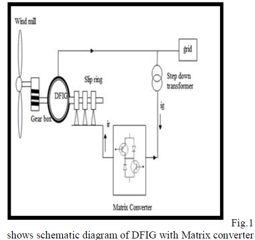
| Aero turbines convert energy in moving air to rotary mechanical energy. In general they require pitch control and yaw control for proper operation. A mechanical interface consisting of a step up gear and a suitable coupling transmits the rotary mechanical energy to an electrical generator[6]. The output of this generator connected to the load or grid. Fig.1shows wind turbine connected to DFIG, with stator is connected directly to grid. And rotor is connected through any power converter to grid. Fig1.shows DFIG rotor connected to grid through matrix converter. |
 |
| The matrix converter has several advantages over AC/DC/AC type power frequency converters. It can be produced sinusoidal input and output waveforms without harmonics [5] [8]. The energy flow capability of matrix converter is bidirectional. The input power factor can be fully controlled. It requires minimal energy storage requirements. Therefore it can be reduced to get rid of bulky and lifetime-limited energy storing capacitors. Figure.2 shows Matrix converter is an AC/AC converter .The uncontrolled AC is converted into controlled AC. At present many advantages are highlight in this converter. It has nine bidirectional switches and any output phase can be connected to any other input phase. |
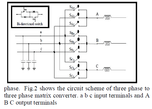 |
| A three phase voltage-fed system, usually grid can be connected to input terminals of the converter..While the output terminals are connected to three phase current-fed system. Fig.2 shows both capacitive and inductive filter on voltage-fed side and current-fed side respectively. The size of this filters are inversely proportional to matrix converter switching frequency [3]. |
| With the nine bidirectional switches of matrix converter can be grouped into three. Group 1 consists of six combinations when each output phase is connected to different input phase. In group II, there are three subgroups each having six combinations with two output phases short-circuited. Group III includes three combinations with all output phases short-circuited. |
| There are 2 following constraints are carried out. |
| 1) The input phases of matrix converter should never be short- circuited. |
| 2) The output phases of matrix converter should never be open circuited. |
| Based on these constraints a three phase to three phase matrix converter has 27 switching combinations. |
| The main application of matrix converter is |
| 1) Cement and ball mill drives |
| 2) Rolling mill drives |
| 3) Slip-power recovery scherbius drives[4] [5] |
| 4) Variable-speed, constant frequency (VSCF) power generation for aircraft 400HZ power supplies |
| Fig shows simplified representation of matrix converter system. The three phase input voltages of matrix converter can be expressed as |
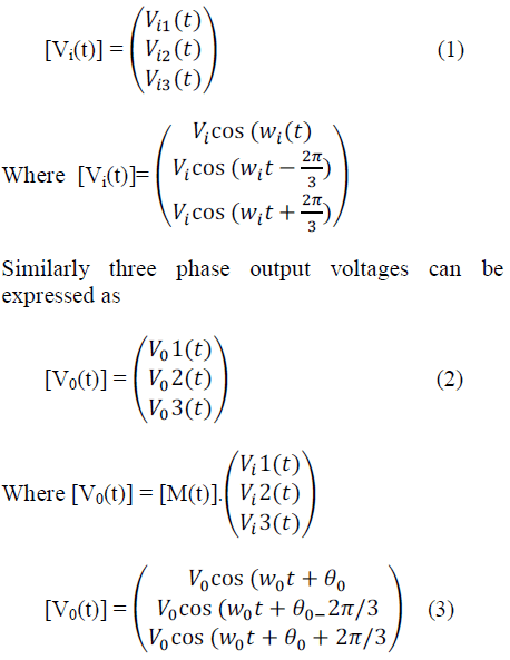 |
| Where θis an arbitrary output voltage phase angle [9]. M(t) is expresses as switching function that must satisfy the above stated condition. |
MATRIX CONVERTER OPERATION AND CONTROL |
| Matrix converter can be used to direct conversion of generator variable AC frequency into the grid constant AC frequency. So it is also called AC-AC converter. The control of input and output voltage waveforms of proposed converter can be achieved through PWM technique. Simulation results show how the converter can operate with any input and output voltages, current, frequencies and power factor power factors while maintaining constant dc voltages across all switch cell capacitor. The PWM is a modulation technique that conforms the width of pulse, formally the pulse duration, based on signal information. Its main use to allow the control of power supplied to electrical devices, especially to inertial load such as motors. In addition ,PWM is one of the two principal algorithms used in photovoltaic solar battery charges other being MPPT. The main advantage of PWM is that power loss in switching devices is low. When a switch is off there is practically no current, and when it is on, there is almost no voltage drop across the switch. The stator of DFIG is directly connected to the grid and rotor is connected to the grid through power electronic converters such as Back to Back converters, matrix converters etc. But Back to Back converters have more disadvantage than matrix converters. Back to Back converters consist of RSC and GSC. The Control of these two converters are very difficult. The matrix converter has many advantages over other AC-AC converters. The advantages of MC are: |
| 1. It consist of a single converter without have any energy storage requirements in the circuit. Thus MC can be packed into a smaller enclosure |
| 2. It can be provided with sinusoidal input and output waveforms of voltage and current |
| 3. It has capability to control input displacement factor |
| 4. It is capable of bidirectional power flow with fourquadrant switching system. |
SIMULATION DIAGRAM |
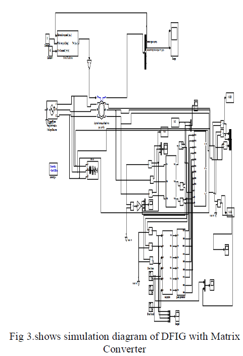 |
| The DFIG technology allows extracting maximum energy from the wind for low speed by optimizing turbine speed. While minimizing mechanical stress on the turbine during gusts of wind. The optimum wind speed is propotional to the wind speed. Another advantage of the DFIG technology is the ability for power electronic converters to generate or absorb reactive power. |
COMMENTS ON RESULTS |
| DFIG based wind turbine consists of RSC and GSC. The RSC applies the voltage to the rotor windings of DFIG. The purpose of RSC is to control the rotor currents such that the rotor flux position is optimally oriented with respect to the stator flux in order that the desired torque is developed at the shaft of the machine. |
SIMULATION RESULTS |
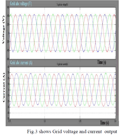
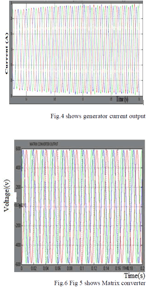
| For the above test system, the output voltage and current waveforms for DFIG based wind turbine by Matrix converter. And evaluate the difference between conventional crowbar protection scheme. |
 |
 |
CONCLUSION |
| The DFIG technology allows extracting maximum energy from the wind for low speed by optimizing turbine speed, while minimizing mechanical stress on the turbine during gusts of wind. The maximum turbine speed is proportional to the wind speed. Another advantage of the DFIG technology can be generates or absorb reactive power using Matrix converter. And power transfer in DFIG wind farm by Matrix converter. Matrix converter with DFIG is simulated in power system block. |
References |
|