Keywords
|
| Space-Time Block Codes, Diversity, Multiple Input Multiple Output (MIMO), Bit Error Rate (BER). |
INTRODUCTION
|
| Wireless Communications is going under explosive growth In the search for the most appropriate multiple access Technology for the third-generation wireless systems, a number of new multiple access schemes have been proposed (e.g., wideband CDMA schemes. TDMA based schemes and TD-CDMA). Digital Communication employing Multiple-Input-Multiple-Output has emerged a most significant technical breakthroughs in wireless communication. Internet wireless network such as broadband wireless access systems, wireless local area networks (WLAN), WCDMA Networks, third-generation (3G) and beyond The basic concept behind MIMO is that signal transmit (TX) antenna at one end and receive antenna at other such that the quality (BER) for each MIMO user will be improved. In MIMO system, space time signal processing is employed, in which time is complemented with the spatial dimension essential in the multiple spatially distributed antenna. MIMO effectively takes advantage of random fading [1]-[3] and multi path delay spread [4], [5] for multiplying transfer rates. This paper discusses the recent advances in MIMO systems. Here will try to determine the optimum coding scheme to be employed in modern MIMO systems for better data throughput and better BER performances. |
| This paper is organized as follows: In section II we will present an overview of system model for MIMO systems. Here we will highlight basic spatial multiplexing (SM) scheme using multiple transmit and receive antenna. In section III, we will explore about STB codes and determine optimum diversity to be employed in our intended system finally section IV concluded this paper. |
SYSTEM MODEL FOR MIMO SYSTEMS
|
| In the conventional smart antenna technology only the transmitter or the receiver is equipped with more than one element, more specifically at the base station (BTS), which is economically more feasible. In MIMO where data transmitted over a matrix rather than a vector channel, creates new and enormous opportunities. MIMO systems can provide a joint transmit-receive diversity gain, as well as array gain upon coherent combining of the antenna elements. Now, we will summarize different MIMO transmission schemes and give some basic theory behind them. |
| Modern transmission schemes over MIMO channels can be broadly divided under two categories: data rate maximization and diversity maximization schemes. The first type works on improving the average capacity behaviour. In the second type, one tries to minimize the outage probability by jointly encoding the individual’s streams in order to protect transmission against errors. |
| If a high-rate bit stream is decomposed into three independent 1/3-rate bit sequences which are transmitted simultaneously using multiple antennas thus utilizing one third of available spectrum. The signals naturally mix together in the wireless channel as they use the same frequency spectrum. At the receiver after identifying the mixing matrix through training symbols, the individual bit streams are separated and estimated. This is same as solving three unknowns using three linear equations. Here, the objective is to perform spatial multiplexing as we send as many independent as we have antenna for specific error rate. |
| Now, we will briefly review the basics of consider a baseband representation for Alamouti with two antennas at the transmitter The signal c1 emitted from antenna 1 and signal c2 from antenna1 and the c1 is transmitted from antenna 2. Here we assume that above channel, remain constant over time. The received signal can be expressed as: |
 |
 |
| Here n1 and n2 are the AWGN. Again we define the signal vector r = [r1r2*] T, the code symbol vector [c2] T, and the noise vector n – [n1n2*] T, we can get matrix equation as |
 |
| Here channel matrix H is defined as |
 |
| Usually used for transmit diversity in the MISO case, and readily extended to the MIMO case. When the receiver uses MRX antennas, the received signal vector X antenna m is |
 |
| Nm is the noise vector and Hm is the channel matrix two TX antenna to the Mth receive antenna. |
VARIOUS STBCS AND THEIR DIVERSITY ORDER
|
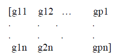
| STB code describes the relation between the original transmitted signal x and the signal replicas created at the transmitter matrix of a STB code is given below |
 |
| Where gij represent linear combinations of the symbols which transmitted simultaneously from TX antenna TX1, TX2,…,TXp for I= 1, 2, …..p. Here code rate defined as |
 |
| `Where k is number of transmitted symbols and n in number of time slots. There are different types of STB codes depending upon the diversities at transmit and receiving ends. |
| A. Space-Time Code G2 having Diversity Four (2X2) |
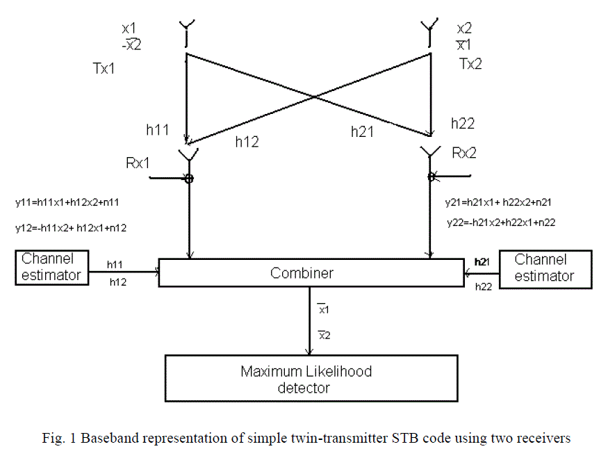
| Here we will discuss specific case of two transmitter and two receivers, as shown in fig.1. In fig.1.we have first receiver at Rx1, |
 |
 |
| and at receiver Rx2, we have |
 |
 |
| At the combiner, the received signal is combined to extract the transmitted signals x1 and x2 from received signal y11, y22, y21 and y12 according to |
 |
 |
| On simplification we can obtain |
 |
 |
| Signals x1 and x2 are finally derived and passed to maximum likelihood detector where the transmitted detector where the transmitted signal is evaluated calculating the minimum Euclidean distance. |
| B. Simulation Result |
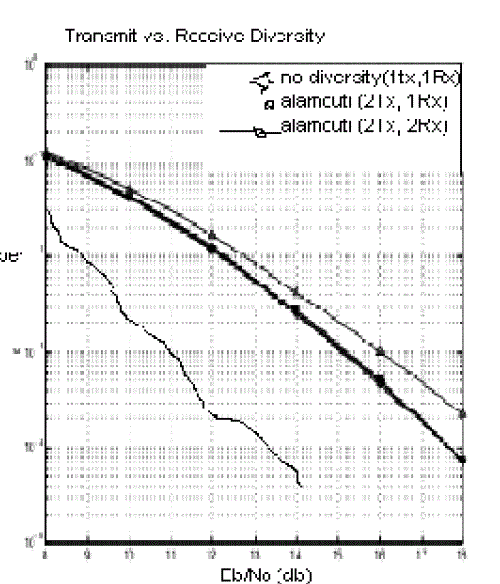
| In fig. 2 we provide Bit Error Rate (BER) for BPSK modulation with Space Time Block Code (STBC) for different values of SNR (Eb/No). Using Space Time Block Coding scheme can help in reducing the Bit Error Rate (BER). It is seen that at Eb/No=10 db the value of BER for Alamouti (2Tx and 2 Rx) Scheme it is about 10-4, for Alamouti (2Tx and1Rx) system it is 10-2.5, and for no diversity(1Tx and 1Rx) it is 10-19. |
| Again, for a BER value of 10-2, the value for Alamouti(2Tx and 2Rx) scheme it is about 3 db, for Alamouti(2Tx and @Rx) system it is 8db, and for no diversity(1Tx and 1Rx), it is 14 db. |
| Hence, it can be concluded out of the following diversity Schemes No Diversity (1Tx and 1Rx), Alamouti (2Tx and 2Rx2x2 MIMO systems using Space Time Block Code scheme has The least Bit Error Rate for given values of Eb/No. |
CONCLUSION
|
| In this paper, we provided a brief analysis of Space Time Block Codes for transmission using multiple transmit and receive antennas including assessment of their performance by computer simulation. The primary purpose of the diversity is to have better convergence rate less Bit Error diversity is to have better convergence rate less Bit Error Rate (BER) without any change in transmitted power and bandwidth. To mitigate the Effect of fading, we used diversity and investigated that BER Decreases significantly after applying Alamouti (2Tx and 2Rx) Scheme. Simulation results were provided to demonstrate that significantly gain Rate (BER) without any change in transmitted power and receiving antennas. |
ACKNOWLEDGMENT
|
| We express our sincere thanks to Dr. Monica Vishwakarma, Principal NIIST Bhopal for her useful guidance for carrying out work |
Figures at a glance
|
 |
 |
| Figure 1 |
Figure 2 |
|
| |
References
|
- Foschini, G. J. and Gans, M. J., “On Limits of Wireless Communications in a Fading Environment When Using Multiple Antennas,” Wireless Personal Communications, Vol. 6, pp. 311-315, Mar. 1998.
- Raleigh, G. and Cioffi, J. M., “Spatial-Temporal Coding for Wireless Communications,” IEEE Transactions on Communications, Vol. 46, pp. 357-366, 1998.
- Telatar. I. E., “Capacity of Multi Antenna Gaussian Channels,” AT&T Laboratories Internal Technical Memorandum, Jun. 1995.
- Rappaport, T. S., “Wireless Communication Principles and Practice,” Prentice Hall, 2nd Edition, 2002.
- Boleskei, H., Gesbert, D., and Paulraj, A. J., “On the Capacity of OFDM-Based Spatial Multiplexing Systems,” IEEE Transactions on Communications, Vol. 50, pp. 225-234, Feb. 2002.
- Alamouti, S. M., “A Simple Transmit Diversity Technique for Wireless Communications,” IEEE Journal on Selected Areas in Communications, Vol. 16, pp. 1451-1458, Oct.1998.
|